TS-7180
| Note: | This manual is incomplete at this time and is subject to change without warning while the TS-7180 is in its Engineering Sampling phase. |
 | |
| Product Page | |
| Product Images | |
| Specifications | |
| Documentation | |
|---|---|
| Schematic | |
| Mechanical Drawing | |
| FTP Path | |
| Processor | |
| NXP (née Freescale) i.MX6ul 696MHz Arm® Cortex®-A7 processor | |
| i.MX6ul Product Page | |
| CPU Documentation |
Overview
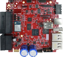
The TS-7180 is an SBC designed for low power systems and is ideal for remote deployment and fleet tracking.
Getting Started
A Linux PC is recommended for development. For developers who use Windows, virtualized Linux using VMWare or similar are recommended in order to make the full power of Linux available. The developer will need to be comfortable with Linux anyway in order to work with embedded Linux on the target platform. The main reasons that Linux is useful are:
- Linux filesystems on the microSD card can be accessed on the PC.
- More ARM cross-compilers are available.
- If recovery is needed, a bootable medium can be written.
- A network filesystem can be served.
- Builds such as Linux kernel, buildroot, yocto, distro-seed will not work from WSL1/2 on a case insensitive filesystem.
| WARNING: | Be sure to take appropriate Electrostatic Discharge (ESD) precautions. Disconnect the power source before moving, cabling, or performing any set up procedures. Inappropriate handling may cause damage to the board. |
Powering up
The TS-7180 typically receives power through a two-pin, 8-28 VDC terminal block connector to the right of the USB-B console connector. From this perspective, the plus (+) side is on the left, and the minus (-) side is on the right. The polarity for the power connection is marked on the enclosure, and is also illustrated in the section on the power connector.
If a power supply is ordered with the TS-7180, it will include the correct terminal block connected to the power supply. Otherwise, the terminal block alone will ship with the unit.
Once power is applied the device will output information via the built in-USB console.
The first output is from the Secondary Program Loader (SPL) and then U-Boot:
U-Boot SPL 2020.01-40207-ge5e6ccfb43 (Feb 07 2022 - 11:26:23 -0700)
Trying to boot from MMC2


U-Boot 2020.01-40207-ge5e6ccfb43 (Feb 07 2022 - 11:26:23 -0700)

CPU:   Freescale i.MX6UL rev1.2 696 MHz (running at 396 MHz)
CPU:   Automotive temperature grade (-40C to 125C) at 44C
Reset cause: WDOG
Model: embeddedTS i.MX6ul TS-7180
DRAM:  1 GiB
MMC:   FSL_SDHC: 0, FSL_SDHC: 1
Loading Environment from MMC... OK
In:    serial
Out:   serial
Err:   serial
FPGA:  Rev 15
Net:   eth0: ethernet@20b4000, eth1: ethernet@2188000
Press ESC twice to abort autoboot in 3 second(s)
The SPL, U-Boot and its environment are loaded from the eMMC boot flash (/dev/mmcblk1boot0). This a hardware partition that is independent of the main flash on the eMMC (/dev/mmcblk1). From here, U-Boot runs the script that is in the user-customizable bootcmd environment variable. This by default checks for boot files on the first USB mass storage, SD card, and eMMC. From here the board will boot to our default #Debian image.
The SPL is a tiny, initial stage that U-Boot introduced in recent years to replace the Device Configuration Data block that used to be prepended to U-Boot images. It loads into the CPU's small on-board SRAM and handles early hardware initialization (such as setting up the DRAM controller) required to load the next, larger stage.
| Note: | U-Boot images or boards with build dates prior to February, 2022 may display differently and/or emit benign error messages such as those below. Typing env save will hide these messages, but doing so is not required to function correctly.
|
When using U-Boot's default configuration, the message "*** Warning - bad CRC, using default environment" can be safely ignored. The message indicates that the area(s) of eMMC used for storing the U-Boot environment is uninitialized or has been otherwise overwritten by programs other than U-Boot itself.
The "using MAC address from ROM" warning indicates that the board is using the pre-programmed MAC addresses that are fused into the CPU. All boards are assigned two such unique MAC addresses, so this message is repeated twice. Even with current U-Boots, this message typically appears after a env default -a was run, since that command restores U-Boot's hard-coded environment that lacks board-specific environment variables).
Connect USB Console
The board includes a USB-B header connected to the onboard preprogrammed microcontroller. This acts as a USB serial device using the CP210x Virtual COM port. Most operating systems have built-in support for this device, however drivers are available here.
Console from Linux
There are many serial terminal applications for Linux, three common used applications are picocom, screen, and minicom. These examples demonstrate all three applications and assume that the serial device is "/dev/ttyUSB0" which is common for USB adapters. Be sure to replace the serial device string with that of the device on your workstation.
picocom is a very small and simple client.
sudo picocom -b 115200 /dev/ttyUSB0
screen is a terminal multiplexer which happens to have serial support.
sudo screen /dev/ttyUSB0 115200
Or a very commonly used client is minicom which is quite powerful but requires some setup:
sudo minicom -s
- Navigate to 'serial port setup'
- Type "a" and change location of serial device to "/dev/ttyUSB0" then hit "enter"
- If needed, modify the settings to match this and hit "esc" when done:
     E - Bps/Par/Bits          : 115200 8N1
     F - Hardware Flow Control : No
     G - Software Flow Control : No
- Navigate to 'Save setup as dfl', hit "enter", and then "esc"
Console from Windows
Putty is a small simple client available for download here. Open up Device Manager to determine your console port. See the putty configuration image for more details.


First Linux Boot
When booting with the default settings, a shipped board will boot to the eMMC. The eMMC by default are pre-programmed with our default Debian 10 Buster image. After Linux boots it will ask the user to log in with a username and password. This uses "root" as the username with no password. This can be changed after logging in with the command "passwd" to set an account password.
From the Linux prompt you can now begin testing out hardware, or beginning your application development.
U-Boot
U-Boot Environment
The U-Boot environment on the TS-7180 is stored in the on-board eMMC flash.
# Print all environment variables
env print -a

# Sets the variable bootdelay to 5 seconds
env set bootdelay 5;

# Variables can also contain commands
env set hellocmd 'led red on; echo Hello world; led green on;'

# Execute commands saved in a variable
env run hellocmd;

# Commit env changes to the spi flash
# Otherwise changes are lost
env save

# Restore env to default
env default -a

# Remove a variable
env delete emmcboot
Accessing the U-Boot Environment from Linux
Recent Debian releases from embeddedTS include the u-boot-tools package, which provides the fw_printenv and fw_setenv commands. They are analogous to the env print and env set commands in U-Boot.
One important difference is that to alter the U-Boot Environment, the boot partition must first be made writable. For an environment in the on-board eMMC, this is how to do so:
DEV_NAME=$(basename $(awk '/^\// {print $1;exit;}' /etc/fw_env.config))
echo 0 > /sys/block/${DEV_NAME}/force_ro
From that point up until when a 1 is written in the above example instead of 0 (or until after a reboot), all uses of fw_setenv will immediately update the environment. There is no need for (nor equivalent to) env save command.
Note that the /etc/fw_env.config provided with our Debian releases expects to find the environment in the boot partition of our boards' eMMC flash. That is expected to match where U-Boot keeps its environment.
U-Boot Commands
# The most important command is
help
# This can also be used to see more information on a specific command
help i2c

# Boots into the binary at $loadaddr.  This file needs to have
# the uboot header from mkimage.  A uImage already contains this.
bootm
# Boots into the binary at $loadaddr, skips the initrd, specifies
# the fdtaddr so Linux knows where to find the board support
bootm ${loadaddr} - ${fdtaddr}

# Get a DHCP address
dhcp
# This sets ${ipaddr}, ${dnsip}, ${gatewayip}, ${netmask}
# and ${ip_dyn} which can be used to check if the dhcp was successful

# These commands are used for scripting:
false # do nothing, unsuccessfully
true # do nothing, successfully

# This command lets you set fuses in the processor
# Setting fuses can brick your board, will void your warranty,
# and should not be done in most cases
fuse

# Control LEDs
led red on
led green on
led all off
led red toggle

# This command is used to copy a file from most devices
# Load kernel from SD
load mmc 0:1 ${loadaddr} /boot/uImage
# Load Kernel from eMMC
load mmc 1:1 ${loadaddr} /boot/uImage


# You can view the fdt from u-boot with fdt
load mmc 0:1 ${fdtaddr} /boot/imx6ul-ts7180.dtb
fdt addr ${fdtaddr}
fdt print

# You can blindly jump into any memory
# This is similar to bootm, but it does not use the
# u-boot header
load mmc 0:1 ${loadaddr} /boot/custombinary
go ${loadaddr}

# Browse fat,ext2,ext3,or ext4 filesystems:
ls mmc 0:1 /

# Access memory like devmem in Linux, you can read/write arbitrary memory
# using mw and md
# write
mw 0x10000000 0xc0ffee00 1
# read
md 0x10000000 1

# Test memory.
mtest

# Check for new SD card
mmc rescan
# Read SD card size
mmc dev 0
mmcinfo
# Read eMMC Size
mmc dev 1
mmcinfo

# The NFS command is like 'load', but used over the network
dhcp
env set serverip 192.168.0.11
nfs ${loadaddr} 192.168.0.11:/path/to/somefile

# Test ICMP
dhcp
ping 192.168.0.11

# Reboot
reset

# Delay in seconds
sleep 10

# You can load HUSH scripts that have been created with mkimage
load mmc 0:1 ${loadaddr} /boot/ubootscript
source ${loadaddr}

# Most commands have return values that can be used to test
# success, and HUSH scripting supports comparisons like
# test in Bash, but much more minimal
if load mmc 1:1 ${fdtaddr} /boot/uImage;
	then echo Loaded Kernel
else
	echo Could not find kernel
fi

# Commands can be timed with "time"
time bdinfo

# Print U-boot version/build information
version
Debian 10
Debian is a community run Linux distribution. Debian provides tens of thousands of precompiled applications and services. This distribution is known for stability and large community providing support and documentation. The installation is specific to our board, but most Debian documentation applies:
Debian 10 - Getting Started and writing an Image
Once installed, the default user is "root" with no password.
This image can be written to a USB drive, a µSD card, or to eMMC. For development, a USB thumbdrive will be simplest. If a bootable USB drive is connected this will take priority over other boot media. Plug in a USB drive and check the last output from "dmesg" to get the USB disk. For example, this may be /dev/sdc.
# Erase all older partitions
sudo sgdisk --zap-all /dev/sdc
# Create one GPT Linux partition
sudo sgdisk -n 0:0:0 -t 0:8300 /dev/sdc
# Create a filesystem and mount
sudo mkfs.ext4 /dev/sdc1
sudo mkdir /mnt/usb/
sudo mount /dev/sdc1 /mnt/usb/
# Extract downloaded image:
sudo tar --numeric-owner -xf ts7180-debian-buster-latest.tar.bz2 -C /mnt/usb/
sudo chmod 755 /mnt/usb/
sudo umount /mnt/usb/
These commands will also work while booted from a USB drive to rewrite the eMMC. Instead of /dev/sdc you would use /dev/mmcblk1, and instead of /dev/sdc1 you would use /dev/mmcblk1p1.
Debian 10 - Configuring the Network
The network in Debian is configured /etc/network/interfaces.d/. For complete documentation, see Debian's documentation here
Some common examples are shown below.
DHCP on eth0. Create the file: /etc/network/interfaces.d/eth0
auto eth0
allow-hotplug eth0
iface eth0 inet dhcp
Static IP on eth0. Create the file /etc/network/interfaces.d/eth0
auto eth0
iface eth0 inet static
    address 192.0.2.7/24
    gateway 192.0.2.254
These will take effect on the next boot, or by restarting the networking service:
service networking restart
Debian 10 - WIFI Client
| Note: | The latest image for this platform as of April 28th, 2022 has known issues with the Wi-Fi driver due to incompatibility with cfg80211 powersave modes.
If using Wi-Fi, it is strongly recommended to bring up the Wi-Fi interface, and then run This issue will be addressed in future images and has already been addressed in our kernel sources. We will continue to provide updates as we receive them from the Wi-Fi module manufacturer. |
Wireless interfaces are also managed with configuration files in "/etc/network/interfaces.d/". For example, to connect as a client to a WPA network with DHCP. Note some or all of this software may already be installed on the target SBC.
Install wpa_supplicant:
apt-get update && apt-get install wpasupplicant -y
Run:
wpa_passphrase youressid yourpassword
This command will output information similar to:
 network={
 	ssid="youressid"
 	#psk="yourpassword"
 	psk=151790fab3bf3a1751a269618491b54984e192aa19319fc667397d45ec8dee5b
 }
Use the hashed PSK in the specific network interfaces file for added security. Create the file:
/etc/network/interfaces.d/wlan0
allow-hotplug wlan0
iface wlan0 inet dhcp
    wpa-ssid youressid
    wpa-psk 151790fab3bf3a1751a269618491b54984e192aa19319fc667397d45ec8dee5b
To have this take effect immediately:
service networking restart
For more information on configuring Wi-Fi, see Debian's guide here.
Debian 10 - WIFI Access Point
| Note: | The latest image for this platform as of April 28th, 2022 has known issues with the Wi-Fi driver due to incompatibility with cfg80211 powersave modes.
If using Wi-Fi, it is strongly recommended to bring up the Wi-Fi interface, and then run This issue will be addressed in future images and has already been addressed in our kernel sources. We will continue to provide updates as we receive them from the Wi-Fi module manufacturer. |
First, hostapd needs to be installed in order to manage the access point on the device:
apt-get update && apt-get install hostapd -y
| Note: | The install process will start an unconfigured hostapd process. This process must be killed and restarted before a new hostapd.conf will take effect. |
Edit /etc/hostapd/hostapd.conf to include the following lines:
interface=wlan0
driver=nl80211
ssid=YourAPName
channel=1
| Note: | Refer to the kernel's hostapd documentation for more wireless configuration options. |
To start the access point launch hostapd:
hostapd /etc/hostapd/hostapd.conf &
This will start up an access point that can be detected by WIFI clients. A DHCP server will likely be desired to assign IP addresses. Refer to Debian's documentation for more details on DHCP configuration.
Wi-Fi Concurrent Client / Access Point
| Note: | The latest image for this platform as of April 28th, 2022 has known issues with the Wi-Fi driver due to incompatibility with cfg80211 powersave modes.
If using Wi-Fi, it is strongly recommended to bring up the Wi-Fi interface, and then run This issue will be addressed in future images and has already been addressed in our kernel sources. We will continue to provide updates as we receive them from the Wi-Fi module manufacturer. |
The Wi-Fi device on this platform supports concurrent operation of client and access point (STA and AP). Please see the "Wi-Fi Client" section above first to connect the Wi-Fi module, in STA mode, to an external AP. This demo showcases the Wi-Fi module starting its own AP mode via hostapd with a simple static IP address while also being concurrently connected to a separate AP.
The 'hostapd' utility is used to manage the access point of the device. This is usually installed by default, but can be installed with:
apt-get update && apt-get install hostapd -y
| Note: | The install process may start an unconfigured 'hostapd' process. This process must be killed before moving forward. |
Modify the file /etc/hostapd/hostapd.conf to have the following lines:
ssid=YourWiFiName
wpa_passphrase=Somepassphrase
interface=p2p0
auth_algs=3
channel=<channel>
driver=nl80211
hw_mode=g
logger_stdout=-1
logger_stdout_level=2
max_num_sta=5
rsn_pairwise=CCMP
wpa=2
wpa_key_mgmt=WPA-PSK
wpa_pairwise=TKIP CCMP
| Note: | The channel used for AP must match the channel the STA is using! Be sure to set 'channel=...' in the above file to a proper channel number. |
| Note: | Refer to the kernel's hostapd documentation for more wireless configuration options. |
In order for the concurrent modes to work, a separate virtual wireless device must first be created. Note that hostapd.conf above lists interface=p2p0, a second interface with this name must be created:
iw wlan0 interface add p2p0 type managed
The access point can then be started and tested by hand:
hostapd /etc/hostapd/hostapd.conf &
An IP address can be set to p2p0:
ifconfig p2p0 192.168.0.1
From this point, other Wi-Fi clients can connect to the SSID YourWiFiName with the WPA2 key Somepassphrase with a static IP in the range of 192.168.0.0/24, and will be able to access the platform at 192.168.0.1. More advanced configurations are also possible, including bridging, routing/NAT, or simply separate networks with the Wi-Fi module connecting to a network and hosting its own private network with DHCP.
Debian 10 - Installing New Software
Debian provides the apt-get system which allows management of pre-built applications. The apt tools require a network connection to the internet in order to automatically download and install new software. The update command will download a list of the current versions of pre-built packages.
apt-get update
A common example is installing Java runtime support for a system. Find the package name first with search, and then install it.
root@tsa38x:~# apt-cache search openjdk
default-jdk - Standard Java or Java compatible Development Kit
default-jdk-doc - Standard Java or Java compatible Development Kit (documentation)
default-jdk-headless - Standard Java or Java compatible Development Kit (headless)
default-jre - Standard Java or Java compatible Runtime
default-jre-headless - Standard Java or Java compatible Runtime (headless)
jtreg - Regression Test Harness for the OpenJDK platform
libreoffice - office productivity suite (metapackage)
openjdk-11-dbg - Java runtime based on OpenJDK (debugging symbols)
openjdk-11-demo - Java runtime based on OpenJDK (demos and examples)
openjdk-11-doc - OpenJDK Development Kit (JDK) documentation
openjdk-11-jdk - OpenJDK Development Kit (JDK)
openjdk-11-jdk-headless - OpenJDK Development Kit (JDK) (headless)
openjdk-11-jre - OpenJDK Java runtime, using Hotspot JIT
openjdk-11-jre-headless - OpenJDK Java runtime, using Hotspot JIT (headless)
openjdk-11-jre-zero - Alternative JVM for OpenJDK, using Zero
openjdk-11-source - OpenJDK Development Kit (JDK) source files
uwsgi-app-integration-plugins - plugins for integration of uWSGI and application
uwsgi-plugin-jvm-openjdk-11 - Java plugin for uWSGI (OpenJDK 11)
uwsgi-plugin-jwsgi-openjdk-11 - JWSGI plugin for uWSGI (OpenJDK 11)
uwsgi-plugin-ring-openjdk-11 - Closure/Ring plugin for uWSGI (OpenJDK 11)
uwsgi-plugin-servlet-openjdk-11 - JWSGI plugin for uWSGI (OpenJDK 11)
java-package - Utility for creating Java Debian packages
In this case, the wanted package will likely be the "openjdk-11-jre" package. Names of packages can be found on Debian's wiki pages or the packages site.
With the package name apt-get install can be used to install the prebuilt packages.
apt-get install openjdk-11-jre
# More than one package can be installed at a time.
apt-get install openjdk-11-jre nano vim mplayer
For more information on using apt-get refer to Debian's documentation here.
Debian 10 - Setting Up SSH
Openssh is installed in our default Debian image, but by default openssh does not permit root logins, and requires a password to be set. Additionally, a host key is required if one hasn't already been created on the target board. To allow remote root login:
sed --in-place 's/#PermitRootLogin prohibit-password/PermitRootLogin yes/' /etc/ssh/sshd_config
systemctl restart ssh.service
/bin/ls /etc/ssh/ssh_host*key >/dev/null 2>&1  || ssh-keygen -A
passwd root # Set any password
If you ssh to this system it will now support ssh as root.
Debian 10 - Starting Automatically
A systemd service can be created to start up headless applications. Create a file in /etc/systemd/system/yourapp.service
[Unit]
Description=Run an application on startup

[Service]
Type=simple
ExecStart=/usr/local/bin/your_app_or_script

[Install]
WantedBy=multi-user.target
If networking is a dependency add "After=network.target" in the Unit section. Once you have this file in place add it to startup with:
# Start the app on startup, but will not start it now
systemctl enable yourapp.service

# Start the app now, but doesn't change auto startup
systemctl start yourapp.service
| Note: | See the systemd documentation for in depth documentation on services. |
Backup / Restore
MicroSD Card
These instructions describe how to create a bootable SD card image. They assume you have an SD card with one partition. Most SD cards ship this way by default, but if you have modified the partitions, you may need to use a utility such as gparted or fdisk to recreate the table with one partition.
These instructions assume your SD interface is /dev/sdc, but plug the SD card into your USB reader and check dmesg to confirm.
On the TS-7180, its on-board SD card reader is /dev/mmcblk1p1.
Running these commands will reflash the SD card to our default latest image.
# Verify nothing else has this mounted
sudo umount /dev/sdc1

sudo mkfs.ext4 -O ^metadata_csum,^64bit /dev/sdc1
sudo mkdir /mnt/sd
sudo mount /dev/sdc1 /mnt/sd/
wget https://ftp.embeddedTS.com/ts-arm-sbc/ts-7180-linux/distributions/debian/ts7180-debian-buster-latest.tar.xz
xzcat ts7180-debian-buster-latest.tar.xz | sudo tar -xhf -C /mnt/sd
sudo umount /mnt/sd
sync
After it is written you can verify the data was written correctly. Reinsert the disk to verify any block cache is gone, then run these:
mount /dev/sdc1 /mnt/sd
cd /mnt/sd/
sudo md5sum -c md5sums.txt
umount /mnt/sd
sync
The md5sums command will report what differences there are, if any, and return if it passed or failed.
eMMC
The simplest way to backup/restore the eMMC is by booting to the SD card and then writing the eMMC image to removable media such as a USB stick.
sudo mkdir /mnt/emmc/
sudo mount /dev/mmcblk1p1 /mnt/emmc/
cd /mnt/emmc/
tar -c . | bzip2 > /path/to/ts7180-backup-image.tar.bz2
cd ../
umount /mnt/emmc/
sync
To write a new filesystem to the TS-7180, first boot to an SD card or USB stick. Then re-image the eMMC:
# The eMMC is /dev/mmcblk1.
#
# Ensure the media has an MBR (not GPT) partition table with exactly one partition.
# Re-partition the device with fdisk or gparted if it isn't already partitioned correctly.

sudo mkdir /mnt/emmc/

sudo mkfs.ext4 -O ^metadata_csum,^64bit /dev/mmcblk1p1
# If the above command fails, complaining of an invalid filesystem option, it is fine to omit that flag:
# An older mkfs.ext4 that doesn’t understand it also can’t create a backwards compatibility issue.

sudo mount /dev/mmcblk1p1 /mnt/emmc/
bzcat /path/to/ts7180-new-image.tar.bz2 | tar -xhf -C /mnt/emmc
umount /mnt/emmc/
sync
Linux Kernel (4.9/LTS)
This platform uses a 4.9 LTS kernel, the source for which is on github in our public github. Compiling the kernel requires an armhf toolchain.
Preparing to Build
We recommend building in a Debian environment, whether actual system (or VM) or a Docker container. Here are the instructions for each:
Building under Debian
Builds require several tools to be present your distribution. For Debian:
| WARNING: | This process may be broken for generic Debian; the commands for Ubuntu should be correct. |
su root

apt-get install curl git build-essential lzop u-boot-tools libncursesw5-dev
echo "deb http://emdebian.org/tools/debian buster main" > /etc/apt/sources.list.d/emdebian.list
curl http://emdebian.org/tools/debian/emdebian-toolchain-archive.key | apt-key add -
dpkg --add-architecture armhf
apt-get update
apt-get install crossbuild-essential-armhf
For Ubuntu:
sudo apt-get update
sudo apt-get install crossbuild-essential-armhf git build-essential lzop u-boot-tools libncursesw5-dev
Building under Docker
Debian only provides their cross compiler for their distribution. Our examples will set up a Docker for Debian to use for development. If using Debian 10 Buster directly, or through a VM then the docker usage can be skipped.
Create a file called "Dockerfile" with these contents:
FROM debian:buster

RUN dpkg --add-architecture armhf

RUN apt-get update && apt-get install -y \
    autogen \
    automake \
    bash \
    bc \
    bison \
    build-essential \
    bzip2 \
    ca-certificates \
    ccache \
    chrpath \
    cpio \
    curl \
    diffstat \
    fakeroot \
    file \
    flex \
    gawk \
    gcc-arm-linux-gnueabihf \
    git \
    gzip \
    kmod \
    libgpiod-dev:armhf \
    libncursesw5-dev \
    libssl-dev \
    libtool \
    locales \
    lzop \
    make \
    multistrap \
    ncurses-dev \
    pkg-config \
    python \
    python3 \
    python3-pip \
    python3-pexpect \
    qemu-user-static \
    rsync \
    socat \
    runit \
    texinfo \
    u-boot-tools \
    unzip \
    vim \
    wget \
    xz-utils

# To make a more readable PS1 to show we are in the Docker
ENV debian_chroot debian_buster
RUN echo "PS1='\${debian_chroot}\\[\033[01;32m\\]@\\H\[\\033[00m\\]:\\[\\033[01;34m\\]\\w\\[\\033[00m\\]\\$ '" >> /etc/bash.bashrc

# Set up locales.  Needed by yocto.
RUN sed -i -e 's/# en_US.UTF-8 UTF-8/en_US.UTF-8 UTF-8/' /etc/locale.gen && \
        echo 'LANG="en_US.UTF-8"'>/etc/default/locale && \
        dpkg-reconfigure --frontend=noninteractive locales && \
        update-locale LANG=en_US.UTF-8

ENV LC_ALL en_US.UTF-8
ENV LANG en_US.UTF-8
ENV LANGUAGE en_US.UTF-8
In the same directory as the file named "Dockerfile" run:
docker build --tag armhf-buster-toolchain .
When this has finished the docker can be used with:
docker run --rm -it --volume $(pwd):/work armhf-buster-toolchain bash
This will map the current directory to /work.
At this point the Debian Docker is ready to compile armhf binaries. For example, create a hello world in your home folder at ~/hello.c
#include <stdio.h>
int main(){
    printf("Hello World\n");
}
To compile this enter the docker with:
docker run -it --volume $(pwd):/work armhf-buster-toolchain bash
# Then from the docker:
cd /work/
arm-linux-gnueabihf-gcc hello.c -o hello
Check "file hello" to verify the binary type:
user@host:~/$ file hello
hello: ELF 32-bit LSB pie executable, ARM, EABI5 version 1 (SYSV), dynamically linked, interpreter /lib/ld-linux-armhf.so.3, for GNU/Linux 3.2.0, BuildID[sha1]=8a8cee3341d3ef76ef6796f72d5722ae9d77c8ea, not stripped
This can also be used to develop against dynamic libraries from Debian. The armhf packages can be installed in the Docker. For example, to link against curl:
# Enter the Docker:
docker run -it --volume $(pwd):/work armhf-buster-toolchain bash
cd /work/

apt-get install libcurl4-openssl-dev:armhf
# Download curl's simple.c example
wget https://raw.githubusercontent.com/bagder/curl/master/docs/examples/simple.c
arm-linux-gnueabihf-gcc simple.c -o simple -lcurl
The "simple" binary is now built for armhf and links dynamically to curl.
This will only retain the armhf libcurl package until the docker is exited. To make the changes permanent, add the package to the Dockerfile and rerun:
docker build --tag armhf-buster-toolchain .
Compiling the Kernel
Once your build environment is prepared:
git clone https://github.com/embeddedTS/linux-lts
# To do a shallow clone of just the latest snapshot of the linux-4.9.y branch, which results in a smaller download size and size on disk, the following command can be used:
# git clone --depth 1 https://github.com/embeddedTS/linux-lts -b linux-4.9.y
cd linux-lts
git checkout linux-4.9.y

## If you are using the 64-bit toolchain:
export CROSS_COMPILE=arm-linux-gnueabihf-
export ARCH=arm
export LOADADDR=0x80800000

make tsimx6ul_defconfig

## Make any changes in "make menuconfig" or driver modifications, then compile
make && make zImage && make modules
Installing the Kernel, Headers, or Modules
To install the headers and/or objects built above to a board, first create a tarball so you can copy it to removable media or another machine.
The following will install the kernel and modules to a temporary directory, and then pack them up in to a single tarball:
TEMPDIR=$(mktemp -d)
mkdir "${TEMPDIR}/boot/"
cp arch/arm/boot/zImage "${TEMPDIR}"/boot/zImage
cp arch/arm/boot/dts/imx6ul*ts*.dtb  "${TEMPDIR}"/boot/
INSTALL_MOD_PATH="${TEMPDIR}" make modules_install
INSTALL_HDR_PATH="${TEMPDIR}" make headers_install
tar czf linux-tsimx6ul-"$(cat include/config/kernel.release)"-"$(date +"%Y%m%d")".tar.gz -C "${TEMPDIR}" .
rm -rf "${TEMPDIR}"
This will output a tarball with the kernel version and short git hash, as well as the date the tarball was created. For example: linux-tsimx6ul-v4.9.171-60-g01e2117e-20190823.tar.gz
This tarball can be directly unpacked to the root folder of a bootable media for the device. It is also possible to unpack it directly on a booted system, however we do not recommend doing so on an active deployed system without extensive testing.
# Unpack it to a mounted disk, this assumes the disk is mounted to "/mnt"
zcat linux-tsimx6ul...tar.gz | tar xh -C /mnt

# Unpack it to the root directory of a booted system
zcat linux-tsimx6ul...tar.gz | tar xh -C /
Troubleshooting
If you experience problems compiling the kernel with the compiler in your distribution, please try whichever of the below toolchains is appropriate for your architecture:
In the case of either toolchain you would run these commands to install them:
chmod a+x poky-*.sh
sudo ./poky-*.sh
Features
ADC
The TS-7180 has four ADC channels, whose inputs are available on the P3 connector as AN_IN_1 through AN_IN_4. Each input may be configured to measure voltage in either one of two ranges (0-2.5V and 0-10.9V) or a 20mA current-loop. Voltage measurements outside those ranges can be accomplished by adding an external voltage divider and then also making corresponding adjustments to the scaling applied in the code examples below.
These ADCs are accessed through the IIO layer in Linux. This provides ADC samples up to 6ksps between all channels. The simplest API for slow speed acquisition is through /sys/:
cat /sys/bus/iio/devices/iio\:device0/in_voltage4_raw
To switch to the 10.9V input range, the appropriate enable must be set high. Each input AN_IN_1 through AN_IN_4 has its own enable, EN_ADC1_10V through EN_ADC4_10V, and these are controlled by GPIO #10 through #13. For example, to switch AN_IN_1 to the 10.9V range, run the following command:
gpioset 5 10=1
Note that the result must now be multiplied by (10.9/2.5). Note also that the input impedance will now be around 2k ohms.
To switch to the 20mA current-loop mode, the appropriate enable must be set high. These are EN_CL_1 through EN_CL_4, and are controlled by GPIO #6 through #9.
# Select 2.5V
gpioset 5 10=0
# Asssert EN_CL_1
gpioset 5 6=1
| # | 'raw' | 2.5/10.9V Select | 20mA Loop Select |
|---|---|---|---|
| AN_IN_1 | in_voltage4_raw | gpio bank 5 io 10 | gpio bank 5 io 6 |
| AN_IN_2 | in_voltage5_raw | gpio bank 5 io 11 | gpio bank 5 io 7 |
| AN_IN_3 | in_voltage8_raw | gpio bank 5 io 12 | gpio bank 5 io 8 |
| AN_IN_4 | in_voltage9_raw | gpio bank 5 io 13 | gpio bank 5 io 9 |
| Note: | The four ADC inputs use the CPU ADC inputs 4,5,8, and 9, corresponding with the 'raw' entries in the above table. |
The libiio library provides simple access to the IO. The fastest API is in C which will get about 6ksps.
/* Build with gcc adc-test.c -o adc-test -liio
 * Gets ~6ksps
 * At the time of writing this does not support the buffer interface */

#include <stdint.h>
#include <stdio.h>
#include <string.h>
#include <assert.h>
#include <stdio.h>
#include <errno.h>
#include <iio.h>

uint32_t scale_mv(uint32_t raw)
{
	/* scale a 0-4095 raw reading to 0-2500 mV */
	uint32_t val = raw * 5000 / (4095 * 2);

	return val;
}

int main(int argc, char **argv)
{
	static struct iio_context *ctx;
	static struct iio_device *dev;
	static struct iio_channel *chn[4];
	int i, ret;
	long long sample;

	ctx = iio_create_default_context();
	assert(ctx);
	dev = iio_context_find_device(ctx, "2198000.adc");
	assert(dev);

	chn[0] = iio_device_find_channel(dev, "voltage4", false);
	chn[1] = iio_device_find_channel(dev, "voltage5", false);
	chn[2] = iio_device_find_channel(dev, "voltage8", false);
	chn[3] = iio_device_find_channel(dev, "voltage9", false);

	for (i = 0; i < 4; i++) {
		ret = iio_channel_attr_read_longlong(chn[i], "raw", &sample);
		assert(!ret);
		printf("AN_CH%d_mv=%d\n", i, scale_mv((uint32_t)sample));
	}

	return 0;
}
The python bindings currently achieve about 2ksps with similar code.
#!/usr/bin/env python

import iio

ctx = iio.Context('local:')
dev = ctx.find_device('2198000.adc')

scan_channels = ["voltage4", "voltage5", "voltage8", "voltage9"]

for n, chan_name in enumerate(scan_channels, start=1):
	chn = dev.find_channel(chan_name)
	raw = int(chn.attrs['raw'].value)

	# Scale 0-4095 raw value to 0-2500(mV)
	scaled = raw * (2.5/4095)

	print('AN_CH{}_V={:.3f}'.format(n, scaled))
Bluetooth
| Note: | The latest image for this platform as of April 28th, 2022 has known issues with the Wi-Fi driver and BLE coexistence due to incompatibility with cfg80211 powersave modes.
If using both Wi-Fi and BLE, it is strongly recommended to bring up the Wi-Fi interface, and then run This issue will be addressed in future images and has already been addressed in our kernel sources. We will continue to provide updates as we receive them from the Wi-Fi module manufacturer. |
The Wi-Fi option for this platform also includes a Bluetooth 5.0 LE module. Support for Bluetooth is provided by the BlueZ project. BlueZ has support for many different profiles for HID, A2DP, and many more. Refer to the BlueZ documentation for more information. Please see our BLE Examples page for information on installing the latest BlueZ release, getting started, and using demo applications.
Both Wi-Fi and Bluetooth can be active at the same time on this platform. Note however, that either the Wi-Fi interface needs to be not brought up if Wi-Fi is unused, or it needs to actively connect to an access point or act as an access point. The Bluetooth module can be activated with the following commands:
For Bluez versions found on Debian Stretch and below:
# Enable Bluetooth, and load the firmware
echo BT_POWER_UP > /dev/wilc_bt
sleep 1
echo BT_DOWNLOAD_FW > /dev/wilc_bt
sleep 1

# Attach the BLE device to the system, increase the baud, and enable flow control
hciattach /dev/ttymxc2 any 115200 noflow
sleep 1
hcitool cmd 0x3F 0x0053 00 10 0E 00 01
stty -F /dev/ttymxc2 921600 crtscts

# Note that no other HCI commands should be used! In older versions of BlueZ, HCI commands exist alongside bluetoothd, however HCI commands can interfere with the bluetoothd stack.
For newer versions of BlueZ found on Debian Buster or newer, or newer versions of BlueZ built from source:
echo BT_POWER_UP > /dev/wilc_bt
sleep 1
echo BT_DOWNLOAD_FW > /dev/wilc_bt
sleep 1

btattach -N -B /dev/ttymxc2 -S 115200 &
sleep 1
bluetoothctl power on
sleep 1
hcitool cmd 0x3F 0x0053 00 10 0E 00 01
kill %1 # This terminates the above btattach command
sleep 1
btattach -B /dev/ttymxc2 -S 921600 &
At this point, the device is running at 921600 baud with flow control, and is fully set up ready to be controlled by various components of BlueZ tools. For example, to do a scan of nearby devices:
bluetoothctl
power on
scan on
This will return a list of devices such as:
root@ts-imx6ul:~# bluetoothctl
Agent registered
[CHG] Controller F8:F0:05:XX:XX:XX Pairable: yes
[bluetooth]# power on
Changing power on succeeded
[CHG] Controller F8:F0:05:XX:XX:XX Powered: yes
[bluetooth]# scan on
Discovery started
[CHG] Controller F8:F0:05:XX:XX:XX Discovering: yes
[NEW] Device 51:DD:C0:XX:XX:XX Device_Name
[NEW] Device 2A:20:E2:XX:XX:XX Device_Name
[CHG] Device 51:DD:C0:XX:XX:XX RSSI: -93
[CHG] Device 51:DD:C0:XX:XX:XX RSSI: -82
[NEW] Device E2:08:B5:XX:XX:XX Device_Name
[CHG] Device 51:DD:C0:XX:XX:XX RSSI: -93
[CHG] Device 2A:20:E2:XX:XX:XX RSSI: -94
[NEW] Device 68:62:92:XX:XX:XX Device_Name
[NEW] Device 68:79:12:XX:XX:XX Device_Name
[bluetooth]# quit
Please note that the Bluetooth module requires the modem control lines CTS and RTS as flow control when running at higher baud rates. It is possible to run the module at the initial 115200 baud if the flow control lines are unwanted.
The module supports some other commands as well:
# Allow the BT chip to enter sleep mode
echo BT_FW_CHIP_ALLOW_SLEEP > /dev/wilc_bt

# Power down the BT radio when not in use
echo BT_POWER_DOWN > /dev/wilc_bt
CAN
The i.MX6UL includes 2 CAN controllers which support the SocketCAN interface, and these are presented on the P3 & P5 connectors (custom populations may differ).
Before proceeding with the examples, see the Kernel's CAN documentation here.
| Note: | The EN_CAN_XVR# line must be set low, by executing the following command: tshwctl -a 20 -w 1 |
This board comes preinstalled with can-utils which can be used to communicate over a CAN network without writing any code. The candump utility can be used to dump all data on the network
## First, set the baud rate and bring up the device:
ip link set can0 type can bitrate 250000
ip link set can0 up

## Dump data & errors:
candump can0 &

## Send the packet with:
#can_id = 0x7df
#data 0 = 0x3
#data 1 = 0x1
#data 2 = 0x0c
cansend can0 -i 0x7DF 0x3 0x1 0x0C
## Some versions of cansend use a different syntax.  If the above
## commands gives an error, try this instead:
#cansend can0 7DF#03010C
The above example packet is designed to work with the Ozen Elektronik myOByDic 1610 ECU simulator to read the RPM speed. In this case, the ECU simulator would return data from candump with:
 <0x7e8> [8] 04 41 0c 60 40 00 00 00
 <0x7e9> [8] 04 41 0c 60 40 00 00 00
In the output above, columns 6 and 7 are the current RPM value. This shows a simple way to prove out the communication before moving to another language.
The following example sends the same packet and parses the same response in C:
#include <stdio.h>
#include <pthread.h>
#include <net/if.h>
#include <string.h>
#include <unistd.h>
#include <net/if.h>
#include <sys/ioctl.h>
#include <assert.h>
#include <linux/can.h>
#include <linux/can/raw.h>

int main(void)
{
	int s;
	int nbytes;
	struct sockaddr_can addr;
	struct can_frame frame;
	struct ifreq ifr;
	struct iovec iov;
	struct msghdr msg;
	char ctrlmsg[CMSG_SPACE(sizeof(struct timeval)) + CMSG_SPACE(sizeof(__u32))];
	char *ifname = "can0";

	if((s = socket(PF_CAN, SOCK_RAW, CAN_RAW)) < 0) {
		perror("Error while opening socket");
		return -1;
	}

	strcpy(ifr.ifr_name, ifname);
	ioctl(s, SIOCGIFINDEX, &ifr);
	addr.can_family  = AF_CAN;
	addr.can_ifindex = ifr.ifr_ifindex;

	if(bind(s, (struct sockaddr *)&addr, sizeof(addr)) < 0) {
		perror("socket");
		return -2;
	}

 	/* For the ozen myOByDic 1610 this requests the RPM guage */
	frame.can_id  = 0x7df;
	frame.can_dlc = 3;
	frame.data[0] = 3;
	frame.data[1] = 1;
	frame.data[2] = 0x0c;

	nbytes = write(s, &frame, sizeof(struct can_frame));
	if(nbytes < 0) {
		perror("write");
		return -3;
	}

	iov.iov_base = &frame;
	msg.msg_name = &addr;
	msg.msg_iov = &iov;
	msg.msg_iovlen = 1;
	msg.msg_control = &ctrlmsg;
	iov.iov_len = sizeof(frame);
	msg.msg_namelen = sizeof(struct sockaddr_can);
	msg.msg_controllen = sizeof(ctrlmsg);
	msg.msg_flags = 0;

	do {
		nbytes = recvmsg(s, &msg, 0);
		if (nbytes < 0) {
			perror("read");
			return -4;
		}

		if (nbytes < (int)sizeof(struct can_frame)) {
			fprintf(stderr, "read: incomplete CAN frame\n");
		}
	} while(nbytes == 0);

	if(frame.data[0] == 0x4)
		printf("RPM at %d of 255\n", frame.data[3]);

	return 0;
}
See the Kernel's CAN documentation here. Other languages have bindings to access CAN such as Python, Java using JNI.
In production use of CAN we also recommend setting a restart-ms for each active CAN port.
ip link set can0 type can restart-ms 100
This allows the CAN bus to automatically recover in the event of a bus-off condition.
COM Ports (see Serial Ports, below )
CPU
The TS-7180 uses a 696MHz NXP i.MX6UL applications processor, which is very similar to the i.MX6 Solo used on the TS-4900. The 6UL has many of the same peripheral IP cores, but it omits the GPU and replaces the ARM Cortex-A9 with a Cortex-A7 CPU to target lower power consumption. Refer to NXP's documentation for more detailed information on the CPU core:
CPU Frequency Scaling
The i.MX6UL CPU has a number of power management features to scale the CPU speed. The maximum speed of the i.MX6UL is 696 MHz; other frequencies possible are 528 MHz, 396 MHz, and 198 MHz. By default, the "ondemand" frequency governor is used. This allows the CPU to run at its lowest speed and increase it when there is computation demand. Other governors are available, see the kernel documentation for a list of these governors and their operation.
The current CPU frequency as well as the governor used are modified by a set of files within the folder "/sys/bus/cpu/devices/cpu0/cpufreq". Some key files are outlined below:
 /sys/bus/cpu/devices/cpu0/cpufreq/cpuinfo_cur_freq - Lists the current frequency
 /sys/bus/cpu/devices/cpu0/cpufreq/scaling_governor - Lists/sets the current frequency governor
 /sys/bus/cpu/devices/cpu0/cpufreq/scaling_setspeed - When govenor is "userspace", set current frequency
 /sys/bus/cpu/devices/cpu0/cpufreq/scaling_available_frequencies - List all available frequencies
 /sys/bus/cpu/devices/cpu0/cpufreq/scaling_available_governors - List all available governors
In order to manually specify a frequency, the frequency governor must be set to userspace. For example, to force the lowest CPU frequency all the time:
echo "userspace" > /sys/bus/cpu/devices/cpu0/cpufreq/scaling_governor
echo "198000" > /sys/bus/cpu/devices/cpu0/cpufreq/scaling_setspeed
Temperature Monitoring
The i.MX6UL CPU has an internal TEMPMON peripheral that is supported by Linux's Thermal Zone management. This on-die sensor is meant to measure of the thermal state of the CPU for throttling control. This can be read via the Linux kernel's sysfs (/sys) interface. The following command returns the temperature in millicelsius:
cat /sys/class/thermal/thermal_zone0/temp
eMMC
This board includes a Micron eMMC module. Our off-the-shelf builds are 4GiB, but up to 64GiB are available for larger builds. The eMMC flash appears to Linux as an SD card at /dev/mmcblk1. Our default programming will include one partition programmed with our Debian image.
eMMC also provides ways to estimate the wear on the module. First, determine your eMMC chipset revision:
root@tsimx6:~# mmc extcsd read /dev/mmcblk1 | grep "CSD rev"
[64446.059203]  mmcblk1: p1
  Extended CSD rev 1.7 (MMC 5.0)
or
root@tsimx6:~# mmc extcsd read /dev/mmcblk1 | grep "CSD rev"
[64446.059203]  mmcblk1: p1
  Extended CSD rev 1.5 (MMC 4.41)
In eMMC revision 5.0 and above, part of the specification includes a way to estimate lifetime of the chipset. For example:
root@tsimx6:~# mmc extcsd read /dev/mmcblk1 | grep -e EXT_CSD_DEVICE_LIFE_TIME -e PRE_EOL
[64618.159298]  mmcblk1: p1
eMMC Life Time Estimation A [EXT_CSD_DEVICE_LIFE_TIME_EST_TYP_A]: 0x01
eMMC Life Time Estimation B [EXT_CSD_DEVICE_LIFE_TIME_EST_TYP_B]: 0x01
eMMC Pre EOL information [EXT_CSD_PRE_EOL_INFO]: 0x01
If you have reconfigured your device as SLC, use TYP_A. If you are using the default MLC setting, use TYP_B. These LIFE_TIME_EST values indicate in 10s of percent how much of the reserve blocks are still available. The 0x1 value indicates < 10%. 0x7 would indicate < 70%.
EXT_CSD_PRE_EOL_INFO can also be used as an early warning indicator.
| Value | Description |
|---|---|
| 0x1 | Normal (< 80% blocks used) |
| 0x2 | Warning (> 80% blocks used) |
| 0x3 | Urgent (>90% blocks used) |
If this is below 5.0, you must use a vendor specific utility. Micron eMMC uses the emmcparm utility. Refer to Micron's TN-FC-25 for the emmcparm utility and related documentation.
Ethernet Ports
The NXP iMX6.UL processor implements two 10/100 Ethernet controllers via external Microchip/Micrel KSZ8081 PHYs and dual RJ45 jacks at the edge of the board. Their MAC addresses will always be sequential and are assigned from a Technologic Systems pool (e8:1a:58 or 00:d0:69).
Support is built into U-Boot as well as the Linux kernel, where standard utilities such as ifconfig/ip can be used to control these interfaces. See the Configuring the Network section for more details. The Precision Time Protocol (PTP) is also supported. For further specifics of this controller, see the CPU manual.

When the optional TS-DC767-POE daughter-card is installed, Power-over-Ethernet (PoE) may be received only via eth1 (ethernet@2188000 in U-Boot), which is the second port in the picture above.
Precision Time Protocol (PTP)
The i.MX6UL CPU Ethernet supports 1588 PTP (PTPv1 & PTPv2).
PTP is supported in Linux via the linuxptp project. This allows synchronizing the system clock to within ±1 us.
Note that Linux kernel version 4.9 or greater is required for PTP support with the i.MX6UL CPU. An example of setting up an ethernet interface with PTP and adjusting the clock based on that is below.
apt-get install linuxptp -y

# For PTP on eth0
phc2sys -s /dev/ptp0 -w &
ptp4l -2 -H -i eth0 -m -p /dev/ptp0 &

# For PTP on eth1
phc2sys -s /dev/ptp1 -w &
ptp4l -2 -H -i eth1 -m -p /dev/ptp1 &
If the clocks are significantly off this may take time for the clocks to converge.
FPGA
FPGA Registers
The recommended way to access the TS-7180 FPGA's forty-four GPIO registers is with Linux's gpioset and gpioget commands (see: GPIO).
The supplied tshwctl utility may also be used to access these registers; run tshwctl -h to see how to use it.
Internally, the TS-7180 accesses its FPGA registers over the 6UL's I2C bus 3. You should only need to do this in programming environments that lack both of those methods mentioned above. The FPGA is available at I2C addresses 0x28-0x2f. First write the address (which is two bytes wide), followed by the data, which is one byte.
The tables below lists all FPGA registers and their functions.
| Address | Bits | Description | ||||||||||||||||||
|---|---|---|---|---|---|---|---|---|---|---|---|---|---|---|---|---|---|---|---|---|
| 0-43[1] | 7:3 | Reserved (Write 0) | ||||||||||||||||||
| 2 | GPIOn Input Data | |||||||||||||||||||
| 1 | GPIOn Output Data | |||||||||||||||||||
| 0 | GPIOn Output Enable | |||||||||||||||||||
| 307 | 7:3 | Reserved (Write 0) | ||||||||||||||||||
| 2:0 | XBee/Nimbelink/MultiTech Cell-modem UART selector (default: 0)
| |||||||||||||||||||
| 308 | 7:3 | Reserved (Write 0) | ||||||||||||||||||
| 2:0 | HD12 UART selector (default: 0)
| |||||||||||||||||||
| 309 | 0 | PWM control[2] | ||||||||||||||||||
| 310 | 7:0 | GPIO chip 0/pin 18 (SPARE_1) MUX[3] (1 = connected, 0 = ignored)
| ||||||||||||||||||
| 311 | 7:0 | Polarity into GPIO chip 0/pin 18 (SPARE_1) MUX[3]
|
- ↑ Each address value corresponds to one GPIO number (n) in the table below.
- ↑ Write 1 to this address to route the CPU PWM to
DIO_1 - ↑ 3.0 3.1 Requires a board with FPGA version 16 or later.
FPGA GPIOs
The FPGA's GPIOs are "gpiochip5" in the Linux GPIO subsystem.
| IO Number | Pad | Direction |
|---|---|---|
| 0 | WIFI_RESET# | OUT |
| 1 | EN_WIFI_PWR | OUT |
| 2 | EN_YEL_LED# | OUT |
| 3 | EN_GREEN_LED# | OUT |
| 4 | EN_RED_LED# | OUT |
| 5 | EN_BLUE_LED# | OUT |
| 6 | EN_CL_1 | OUT |
| 7 | EN_CL_2 | OUT |
| 8 | EN_CL_3 | OUT |
| 9 | EN_CL_4 | OUT |
| 10 | EN_ADC1_10V | OUT |
| 11 | EN_ADC2_10V | OUT |
| 12 | EN_ADC3_10V | OUT |
| 13 | EN_ADC4_10V | OUT |
| 14 | EN_SD_POWER | OUT |
| 15 | EN_USB_HOST_5V | OUT |
| 16 | EN_OFF_BD_5V | OUT |
| 17 | EN_CELL_MODEM_PWR | OUT |
| 18 | EN_NIMBEL_3.3V | OUT |
| 19 | EN_GPS_PWR# | OUT |
| 20 | EN_CAN_XVR# | OUT |
| 21 | EN_232_XVR | OUT |
| 22 | EN_LS_OUT_1 | OUT |
| 23 | EN_LS_OUT_2 | OUT |
| 24 | EN_LS_OUT_3 | OUT |
| 25 | EN_LS_OUT_4 | OUT |
| 26 | EN_LS_OUT_5 | OUT |
| 27 | EN_LS_OUT_6 | OUT |
| 28 | EN_LS_OUT_7 | OUT |
| 29 | MT_RESET# [1] | OUT |
| 30 | Unused | n/a |
| 31 | Unused | n/a |
| 32 | DIG_IN_1 | IN |
| 33 | DIG_IN_2 | IN |
| 34 | DIG_IN_3 | IN |
| 35 | DIG_IN_4 | IN |
| 36 | SD_BOOT_JMP# | IN |
| 37 | DIO_IN_1 | IN |
| 38 | DIO_IN_2 | IN |
| 39 | DIO_IN_3 | IN |
| 40 | DIO_IN_4 | IN |
| 41 | DIO_IN_5 | IN |
| 42 | DIO_IN_6 | IN |
| 43 | DIO_IN_7 | IN |
- ↑ Requires a board with FPGA version 16 or later.
FRAM
This platform supports a soldered-down, non-volatile Ferroelectric RAM (FRAM) device. The Cypress FM25L16B is a 2 KiB FRAM device in a configuration not unlike an SPI EEPROM. The nature of FRAM means it is non-volatile, incredibly fast to write, and is specified with 100 trillion read/write cycles (per each of the 256 sequential 8 byte rows) with a 150 year data retention at temperatures below 65 °C. The device is connected to Linux and presents itself as a flat file that can be read and written like any standard Linux file.
The FRAM can be accessed as a flat file from Linux:
# xxd -a /sys/class/spi_master/spi2/spi2.2/eeprom | head
00000000: 0000 0000 0000 0000 0000 0000 0000 0000  ................
*
000007f0: 0000 0000 0000 0000 0000 0000 0000 0030  ...............0
If U-Boot's bootcount tracking environment variable is enabled, the last byte of FRAM is reserved for storing the boot count, and care should be taken to not overwrite it inadvertently. In U-Boot, the boot count can be accessed with the fram command.
GPIO
The i.MX6UL CPU and FPGA GPIO are exposed using a kernel character device. This interface provides a set of files and directories for interacting with GPIO which can be used from any language that interact with special files in linux using ioctl() or similar. For our platforms, we pre-install the "libgpiod" library and binaries package. Documentation on this package can be found here. This section only covers using these userspace tools and does not provide guidance on using the libgpiod library in end applications. Please see the libgpiod documentation for this purpose.
A user with suitable permissions to read and write /dev/gpiochip* files can immediately interact with GPIO pins. For example, to read the push_sw:
gpioget 2 18 # Returns 0 when pressed, 1 when not
Multiple pins in the same chip can be read simultaneously by passing multiple pin numbers separated by spaces.
This GPIO interface also provides labels for all the I/O. To get a reference from the board of all GPIO run:
gpioinfo
The TS-7180 provides seven IO ports that can sink up to 500mA, or withstand up to 30V at the input. These are available on the P3 connector. DIO_1 through DIO_7 appear as GPIO bank 5 io 37 through 43 (when used as inputs), and as GPIO bank 5 io 22 through 28 (when used as outputs). For example, to read the state of DIO_1, enter the following command:
gpioget 5 37
To drive enable the 500mA sink, enter the following command:
gpioset 5 22=1
gpiochip0 - 32 lines:
	line   0: "BOOT_MODE_0" unused input active-high
	line   1:      unnamed       unused   input  active-high
	line   2:  "I2C_1_CLK"       unused   input  active-high
	line   3:  "I2C_1_DAT"       unused   input  active-high
	line   4:      "ADC_1"       unused   input  active-high
	line   5:      "ADC_2"       unused   input  active-high
	line   6:   "ETH_MDIO"       unused   input  active-high
	line   7:    "ETH_MDC"       unused   input  active-high
	line   8:      "ADC_3"       unused   input  active-high
	line   9:      "ADC_4"       unused   input  active-high
	line  10:      unnamed       unused   input  active-high
	line  11:      unnamed       unused   input  active-high
	line  12:      unnamed       unused   input  active-high
	line  13:      unnamed       unused   input  active-high
	line  14:      unnamed       unused   input  active-high
	line  15:      unnamed       unused   input  active-high
	line  16: "CONSOLE_TXD" unused input active-high
	line  17: "CONSOLE_RXD" unused input active-high
	line  18:    "SPARE_1"       unused   input  active-high
	line  19:     "EN_485"       unused   input  active-high
	line  20:  "UART2_TXD"       unused   input  active-high
	line  21:  "UART2_RXD"       unused   input  active-high
	line  22:  "CAN_2_TXD"       unused   input  active-high
	line  23: "CAN2_RXD_3V" unused input active-high
	line  24:  "UART3_TXD"       unused   input  active-high
	line  25:  "UART3_RXD"       unused   input  active-high
	line  26: "UART3_CTS#"       unused   input  active-high
	line  27: "UART3_RTS#"       unused   input  active-high
	line  28:  "UART4_TXD"       unused   input  active-high
	line  29:  "UART4_RXD"       unused   input  active-high
	line  30:  "UART5_TXD"       unused   input  active-high
	line  31:  "UART5_RXD"       unused   input  active-high
gpiochip1 - 32 lines:
	line   0: "ENET1_RX_DATA0" unused input active-high
	line   1: "ENET1_RX_DATA1" unused input active-high
	line   2: "ENET1_RX_EN" unused input active-high
	line   3: "ENET1_TX_DATA0" unused input active-high
	line   4: "ENET1_TX_DATA1" unused input active-high
	line   5: "ENET1_TX_EN" unused input active-high
	line   6: "ENET1_TX_CLK" unused input active-high
	line   7: "ENET1_RX_ER" unused input active-high
	line   8: "ENET2_RX_DATA0" unused input active-high
	line   9: "ENET2_RX_DATA1" unused input active-high
	line  10: "ENET2_RX_EN" unused input active-high
	line  11: "ENET2_TX_DATA0" unused input active-high
	line  12: "ENET2_TX_DATA1" unused input active-high
	line  13: "ENET2_TX_EN" unused input active-high
	line  14: "ENET2_TX_CLK" unused input active-high
	line  15: "ENET2_RX_ER" unused input active-high
	line  16:     "SD_CMD"       unused   input  active-high
	line  17:     "SD_CLK"       unused   input  active-high
	line  18:      "SD_D0"       unused   input  active-high
	line  19:      "SD_D1"       unused   input  active-high
	line  20:      "SD_D2"       unused   input  active-high
	line  21:      "SD_D3"       unused   input  active-high
	line  22:      unnamed       unused   input  active-high
	line  23:      unnamed       unused   input  active-high
	line  24:      unnamed       unused   input  active-high
	line  25:      unnamed       unused   input  active-high
	line  26:      unnamed       unused   input  active-high
	line  27:      unnamed       unused   input  active-high
	line  28:      unnamed       unused   input  active-high
	line  29:      unnamed       unused   input  active-high
	line  30:      unnamed       unused   input  active-high
	line  31:      unnamed       unused   input  active-high
gpiochip2 - 32 lines:
	line   0: "HD1_SPI_CS"    "spi_imx"  output  active-high [used]
	line   1: "JTAG_FPGA_TCK" unused input active-high
	line   2: "JTAG_FPGA_TMS" unused input active-high
	line   3: "JTAG_FPGA_TDI" unused input active-high
	line   4:      "WDOG#"       unused   input  active-high
	line   5:  "I2C_3_DAT"       unused   input  active-high
	line   6:  "I2C_3_CLK"       unused   input  active-high
	line   7:      unnamed       unused   input  active-high
	line   8: "HD1_I2C_CLK" "scl" output active-high [used]
	line   9: "HD1_I2C_DAT" "sda" output active-high [used]
	line  10: "HD1_DIG_INPUT" unused input active-high
	line  11: "NO_CHRG_JMP#" unused input active-high
	line  12: "EN_NIM_USB#" unused input active-high
	line  13:  "CAN_1_TXD"       unused   input  active-high
	line  14: "CAN1_RXD_3V" unused input active-high
	line  15:  "XBEE_CTS#"       unused   input  active-high
	line  16: "U_BOOT_JMP#" unused input active-high
	line  17:      unnamed       unused   input  active-high
	line  18: "PUSH_SW_CPU#" unused input active-high
	line  19: "NIMBEL_PWR_ON" unused input active-high
	line  20:      unnamed       unused   input  active-high
	line  21:  "UART7_TXD"       unused   input  active-high
	line  22:  "UART7_RXD"       unused   input  active-high
	line  23:        "ID4"       unused   input  active-high
	line  24: "JTAG_FPGA_TDO" unused input active-high
	line  25:  "UART8_TXD"       unused   input  active-high
	line  26:  "UART8_RXD"       unused   input  active-high
	line  27:        "ID1"       unused   input  active-high
	line  28: "ETH_PHY_RESET#" unused input active-high
	line  29:      unnamed       unused   input  active-high
	line  30:      unnamed       unused   input  active-high
	line  31:      unnamed       unused   input  active-high
gpiochip3 - 32 lines:
	line   0:   "EMMC_CLK"       unused   input  active-high
	line   1:   "EMMC_CMD"       unused   input  active-high
	line   2:    "EMMC_D0"       unused   input  active-high
	line   3:    "EMMC_D1"       unused   input  active-high
	line   4:    "EMMC_D2"       unused   input  active-high
	line   5:    "EMMC_D3"       unused   input  active-high
	line   6:  "SPI_4_CLK"       unused   input  active-high
	line   7: "SPI_4_MOSI"       unused   input  active-high
	line   8: "SPI_4_MISO"       unused   input  active-high
	line   9:  "SPI_4_CS#"    "spi_imx"  output  active-high [used]
	line  10:  "MAG_N_IRQ"       unused   input  active-high
	line  11: "FPGA_RESET#" unused input active-high
	line  12: "SPI_3_FPGA_CS#" "spi_imx" output active-high [used]
	line  13:  "SPI_3_CLK"       unused   input  active-high
	line  14: "SPI_3_MOSI"       unused   input  active-high
	line  15: "SPI_3_MISO"       unused   input  active-high
	line  16:      "PWM_5"       unused   input  active-high
	line  17:  "UART6_TXD"       unused   input  active-high
	line  18:  "UART6_RXD"       unused   input  active-high
	line  19:        "ID5"       unused   input  active-high
	line  20:   "GYRO_INT"       unused   input  active-high
	line  21: "6UL_FORCE_5V_ON" unused input active-high
	line  22: "EN_EMMC_3.3V#" "?" output active-low [used]
	line  23: "EN_YEL_LED#" "?" output active-low [used]
	line  24: "EN_RED_LED#" "?" output active-low [used]
	line  25: "EN_GRN_LED#" "?" output active-low [used]
	line  26: "EN_BLU_LED"          "?"  output  active-high [used]
	line  27: "FRAM_SPI_CS#" "spi_imx" output active-high [used]
	line  28: "SD_VSEL_1.8V" unused input active-high
	line  29:      unnamed       unused   input  active-high
	line  30:      unnamed       unused   input  active-high
	line  31:      unnamed       unused   input  active-high
gpiochip4 - 32 lines:
	line   0: "POWER_FAIL"       unused   input  active-high
	line   1:   "FPGA_IRQ"       unused   input  active-high
	line   2:      unnamed       unused   input  active-high
	line   3:  "GPIO_DVFS"          "?"  output  active-high [used]
	line   4:      unnamed       unused   input  active-high
	line   5: "SILAB_C2_CLK" unused input active-high
	line   6: "SILAB_C2_DATA" unused input active-high
	line   7: "SILAB_C2_RESET" unused input active-high
	line   8:    "SPARE_4"       unused   input  active-high
	line   9:      unnamed       unused   input  active-high
	line  10:      unnamed       unused   input  active-high
	line  11:      unnamed       unused   input  active-high
	line  12:      unnamed       unused   input  active-high
	line  13:      unnamed       unused   input  active-high
	line  14:      unnamed       unused   input  active-high
	line  15:      unnamed       unused   input  active-high
	line  16:      unnamed       unused   input  active-high
	line  17:      unnamed       unused   input  active-high
	line  18:      unnamed       unused   input  active-high
	line  19:      unnamed       unused   input  active-high
	line  20:      unnamed       unused   input  active-high
	line  21:      unnamed       unused   input  active-high
	line  22:      unnamed       unused   input  active-high
	line  23:      unnamed       unused   input  active-high
	line  24:      unnamed       unused   input  active-high
	line  25:      unnamed       unused   input  active-high
	line  26:      unnamed       unused   input  active-high
	line  27:      unnamed       unused   input  active-high
	line  28:      unnamed       unused   input  active-high
	line  29:      unnamed       unused   input  active-high
	line  30:      unnamed       unused   input  active-high
	line  31:      unnamed       unused   input  active-high
gpiochip5 - 64 lines:
	line   0: "WIFI_RESET#" unused output active-high
	line   1: "EN_WIFI_PWR" unused output active-high
	line   2:      unnamed       unused   input  active-high
	line   3:      unnamed       unused   input  active-high
	line   4:      unnamed       unused   input  active-high
	line   5:   "FRAM_WP#"       unused   input  active-high
	line   6:    "EN_CL_1"       unused   input  active-high
	line   7:    "EN_CL_2"       unused   input  active-high
	line   8:    "EN_CL_3"       unused   input  active-high
	line   9:    "EN_CL_4"       unused   input  active-high
	line  10: "EN_ADC1_10V" unused input active-high
	line  11: "EN_ADC2_10V" unused input active-high
	line  12: "EN_ADC3_10V" unused input active-high
	line  13: "EN_ADC4_10V" unused input active-high
	line  14: "EN_SD_POWER" "?" output active-high [used]
	line  15: "EN_USB_HOST_5V" unused input active-high
	line  16: "EN_OFF_BD_5V" unused input active-high
	line  17: "EN_AUX_PWR"       unused   input  active-high
	line  18: "EN_NIMBEL_3.3V" unused input active-high
	line  19: "EN_GPS_PWR#" unused input active-high
	line  20: "EN_CAN_XVR#" "en-can" output active-high [used]
	line  21: "EN_232_XVR"       unused   input  active-high
	line  22: "EN_LS_OUT_1" unused input active-high
	line  23: "EN_LS_OUT_2" unused input active-high
	line  24: "EN_LS_OUT_3" unused input active-high
	line  25: "EN_LS_OUT_4" unused input active-high
	line  26: "EN_LS_OUT_5" unused input active-high
	line  27: "EN_LS_OUT_6" unused input active-high
	line  28: "EN_LS_OUT_7" unused input active-high
	line  29:      unnamed       unused   input  active-high
	line  30:      unnamed       unused   input  active-high
	line  31:      unnamed       unused   input  active-high
	line  32:   "DIG_IN_1"       unused   input  active-high
	line  33:   "DIG_IN_2"       unused   input  active-high
	line  34:   "DIG_IN_3"       unused   input  active-high
	line  35:   "DIG_IN_4"       unused   input  active-high
	line  36: "SD_BOOT_JMP#" unused input active-high
	line  37:   "DIO_1_IN"       unused   input  active-high
	line  38:   "DIO_2_IN"       unused   input  active-high
	line  39:   "DIO_3_IN"       unused   input  active-high
	line  40:   "DIO_4_IN"       unused   input  active-high
	line  41:   "DIO_5_IN"       unused   input  active-high
	line  42:   "DIO_6_IN"       unused   input  active-high
	line  43:   "DIO_7_IN"       unused   input  active-high
	line  44:      unnamed       unused   input  active-high
	line  45:      unnamed       unused   input  active-high
	line  46:      unnamed       unused   input  active-high
	line  47:         "N7"       unused   input  active-high
	line  48:         "P7"       unused   input  active-high
	line  49:      unnamed       unused   input  active-high
	line  50:      unnamed       unused   input  active-high
	line  51:      unnamed       unused   input  active-high
	line  52:      unnamed       unused   input  active-high
	line  53:      unnamed       unused   input  active-high
	line  54:      unnamed       unused   input  active-high
	line  55:      unnamed       unused   input  active-high
	line  56:      unnamed       unused   input  active-high
	line  57:      unnamed       unused   input  active-high
	line  58:      unnamed       unused   input  active-high
	line  59:      unnamed       unused   input  active-high
	line  60:      unnamed       unused   input  active-high
	line  61:      unnamed       unused   input  active-high
	line  62:      unnamed       unused   input  active-high
	line  63:      unnamed       unused   input  active-high
GPIOs into the CPU, such as those on the push switch near the row of LEDs (PUSH_SW_CPU#) and internal headers can generate interrupts and be used with gpiomon(1):
root@tsimx6:~# gpiomon 2 18
event: FALLING EDGE offset: 18 timestamp: [1643650592.848516846]
event:  RISING EDGE offset: 18 timestamp: [1643650593.225238304]
^Croot@tsimx6:~#
One way of turning that into something useful would be by running it in a shell script:
while true ; do
      event=$(gpiomon --num-events=1 --falling-edge 2 18)
      echo "received $event"
      # do something
done| Note: | DIO lines on the FPGA (gpiochip5) don't have their own interrupts, thus the gpiomon(1) command does not normally work for them.
|
GPS

The TS-7180 has an optional on-board Telit SL869 GPS receiver, accessible at /dev/ttymxc7, through which the GPS provides NMEA strings. An SMA female connector is provided for attaching an antenna.
The GPS power is controllable through a GPIO. For example:
gpioset 5 19=1 # turn on GPS
gpioset 5 19=0 # turn off GPS
By default, the GPS module is powered on when the board starts up.
A typical way of interfacing with the GPS is using gpsd. For example, under Debian, load these packages:
apt install gpsd gpsd-clients -y
Then edit /etc/default/gpsd and enable and/or change these two variables:
# Devices gpsd should collect to at boot time.
# They need to be read/writeable, either by user gpsd or the group dialout.
DEVICES="/dev/ttymxc7"

# Other options you want to pass to gpsd
GPSD_OPTIONS="-n"
Then restart gpsd:
service gpsd restart
For testing, run gpsmon to see lock, coordinates, and time information.
You will likely want gpsd to start automatically at boot. To make this always happen, type:
systemctl enable gpsd
Finally, the following article describes writing clients that interface with gpsd, which can do so from most programming languages:
Jumpers
The TS-7180 has a set of jumpers located near the SuperCaps on the edge of the SBC.

These jumpers control a number of aspects of the TS-7180's behavior. The jumpers are labeled on the silkscreen rather than numbered:
| Label | Description |
|---|---|
| NO Charge | When jumper is set, disable charging of the SuperCaps. Beneficial for early development and testing. |
| SD Boot | When jumper is set, boot kernel and Debian from the SD card. Otherwise boot kernel and Debian from eMMC. This jumper influences U-Boot behavior. |
| U Boot | When jumper is set, pause booting in U-Boot and drop to a U-Boot shell. Otherwise boot straight to Debian. |
| CAN | When jumper is set, adds a 120 ohm termination resistor across CAN1 H and L pins. (Note: the CAN2 interface always has a 120 ohm termination) |
| 485 | When jumper is set, adds a 120 ohm termination resistor across RS-485 + and - pins. |
LEDs
There are four LEDS on the TS-7180 that may be controlled by the user through the sysfs interface. These are colored yellow, green, red, and blue.
To turn an LED on, write a 1 to 'brightness'. To turn it off again, write a 0.
# Example:  Turn on the Blue LED...
echo 1 > /sys/class/leds/blue-led/brightness

# Turn it off again...
echo 0 > /sys/class/leds/blue-led/brightness
A number of triggers are also available for each LED, including timers, disk activity, and heartbeat. These allow the LEDs to represent various system activities as they occur. See the kernel LED documentation for more information on triggers and general use of LED class devices.
MicroSD Card Interface
The i.MX6ul SDHCI driver supports MicroSD (0-2GB), MicroSDHC (4-32GB), and MicroSDXC(64GB-2TB). The cards available on our website on average support up to 16MB/s read, and 22MB/s write using this interface. Sandisk Extreme cards with UHS support have shown 58MB/s Read and 59MB/s write. The linux driver provides access to this socket at /dev/mmcblk0 as a standard Linux block device.

Seethe IMX6ul reference manual for more information on this controller.
We have performed compatibility testing on the Sandisk MicroSD cards we provide, and we do not suggest switching brands/models without your own qualification testing. Though SD cards in theory will all follow the standard and just work, in practice cards vary significantly and can fail in subtle ways. We do not recommend ATP or Transcend MicroSD cards specifically due to known corruption issues that can occur after many GB of written data.
Our testing has shown that on average microSD cards will last between 6-12TB of written data before showing a single bit of corruption. This is enough for most applications to write for years and not see any issues, but for more reliable consider the eMMC which is expected to last over 100TB of writes. Higher end SD cards can also extend this, but industrial grade SD cards typically carry a cost much higher than the eMMC.
MicroSD cards should not be powered down during a write/erase cycle or you will eventually experience disk corruption. It is not always possible for fsck to recover from the types of failures that will be seen with SD power loss. The system should be designed to avoid power loss to SD cards, or the eMMC module should be used for storage instead which can be configured to be resilient to power loss.
PWM
| WARNING: | This requires FPGA Rev 11 or later |
The TS-7180 provides a single PWM channel, available on DIO_1 (pin #1 of P3-A). Because DIO_1 is a general-purpose IO, to use it as a PWM output it is first necessary to enable such usage by writing to address 309 in the FPGA, as follows:
tshwctl -a 309 -w 1
PWM devices are available though the sysfs filesystem, they will appear at "/sys/class/pwm/pwmchipX/" where X is the PWM channel number. Due to the layout of the PWM controller, each PWM channel is on a separate chip. Normally a single PWM chip can support multiple PWM devices through linux, however in this case each chip only has a single device; pwm0. This device is not enabled by default and must be turned on manually: can be used to control the PWM.
# Each PWM controller has "1" PWM device which will be PWM channel 0
echo 0 > /sys/class/pwm/pwmchipX/export
This will create a pwm0/ directory under each pwmchipX/ directory which will contain the following relevant files.:
| period | Total period, inactive and active time in the PWM cycle specified in nanoseconds. |
| duty_cycle | Active time of the PWM signal specified in nanoseconds. Must be less than the period. |
| enable | Write 1 to enable, 0 to disable |
As an example, this will set a 50khz signal with 50 percent duty cycle on PWM channel 4:
# 20us is the period for 50khz
echo 20000 > /sys/class/pwm/pwmchip4/pwm0/period
echo 10000 > /sys/class/pwm/pwmchip4/pwm0/duty_cycle
echo 1 > /sys/class/pwm/pwmchip4/pwm0/enable
| Note: | The DIO pins on the TS-7180 have a 1.5k pull-up, which means that the rise-time on these outputs is relatively slow. Therefore, you might need to add an off-board pull-up to get a faster rise-time. |
Quadrature & Edge-Counters
Quadrature Counters
The TS-7180 provides three independent quadrature counters. The associated inputs are shown in the table below.
| ||||||||
Each of the quadrature counters (which are in the FPGA) is 16-bits wide, and are accessed via i2c. The addresses are shown below.
| Quad # | MSB | LSB | MSB Alias |
|---|---|---|---|
| Quad0 | 96 | 97 | 98 |
| Quad1 | 99 | 100 | 101 |
| Quad2 | 102 | 103 | 104 |
For example, to read the MSB for Quad1:
tshwctl -r -a 99
The MSB aliases are used to detect 16-bit rollover. If the first reading of the MSB is not equal to the second, overflow/underflow was detected during the read.
Edge-Counters, Period-counters
For each input pin, there is an edge-counter, and a period-counter. The former counts the positive edges on an input pin, while the latter may be used to measure the elapsed time between N positive-edges.
Edge-counters are 16-bits wide, and their addresses are shown in the table below.
| Input | MSB | LSB | MSB Alias |
|---|---|---|---|
| DIG_IN_1 | 105 | 106 | 107 |
| DIG_IN_2 | 108 | 109 | 110 |
| DIG_IN_3 | 111 | 112 | 113 |
| DIG_IN_4 | 114 | 115 | 116 |
| DIO_6_IN | 117 | 118 | 119 |
| DIO_7_IN | 120 | 121 | 122 |
Period counters are 32-bits wide, and their addresses are shown in the table below.
| Input | Byte 3 | Byte 2 | Byte 1 | Byte 0 |
|---|---|---|---|---|
| DIG_IN_1 | 131 | 132 | 133 | 134 |
| DIG_IN_2 | 135 | 136 | 137 | 138 |
| DIG_IN_3 | 139 | 140 | 141 | 142 |
| DIG_IN_4 | 143 | 144 | 145 | 146 |
| DIO_6_IN | 147 | 148 | 149 | 150 |
| DIO_7_IN | 151 | 152 | 153 | 154 |
To use the period counters, it is first necessary to write N (for the number of edges to count) to address 155. This may be done like so:
tshwctl -a 155 -w N
As soon as address 155 is written, counting begins, clocked at 63MHz. After N edges have been detected, the period registers may be read. The frequency of the input may be calculated from the period, as shown here:
frequency = (N * 63000000) / period
Technologic Systems has provided a simple test program for accessing and displaying the values from the quadrature and edge-counters. Download the source tarball here: File:Test-edges.tar.gz
RTC
The TS-7180 includes an ST M41T00S low-power serial real-time clock (RTC) with battery-backup. This is /dev/rtc0 in our images, and is accessed using the standard hwclock command.
Serial Ports
The TS-7180 provides three standard RS-232 ports, and one RS-485 port. A fourth RS-232 port is a non-standard option. All of these ports are presented on the P5 connector. The RS-485 port has auto-transmit-enable and an on-board terminator that may be enabled by installing the "485" jumper (adjacent to the RTC battery).
RS-232 ports 1 through 3
| UART | Linux /dev | Connection on Terminal Block P5-A | To "steal [1]" | TX pin | RX pin |
|---|---|---|---|---|---|
| UART2 | ttymxc1 | TX2/RX2 | 5 | 6 | |
| UART5 | ttymxc4 | TX1/RX1 | 2 | 3 | |
| UART7 | ttymxc6 | TX3/RX3 (unless "stolen") | 4 | 7 | 8 |
- ↑ Writing this value to FPGA address 307 or 308 takes over this UART device for the cell modem or HD12, respectively. While "stolen", this physical RS-232 connection no longer possesses a UART device.
| Note: | The RS-232 transceiver chip on the board must be enabled before those ports can be used. This is done by running the command tshwctl -a 21 -w 3.
|
RS-485
| UART | 485+ | 485- |
|---|---|---|
| ttymxc3 | P5-13 | P5-14 |
RS-485 on the P5 terminal block is accessible via /dev/ttymxc3, unless that device is "stolen" for RS-232 on the XBee/Nimbelink/MultiTech sockets or the HD12 header.
RS-232 port 4 (optional)
Custom boards may provide a fourth RS-232 port on P5, taking over the pins that by default are assigned to the second CAN controller. In this case, the pinout of the additional RS-232 port is:
| UART | TX | RX |
|---|---|---|
| ttymxc7 | P5-10 | P5-11 |
The daughter-card interface (HD12 header) contains TTL-level TX/RX pins that may be used to connect to a CPU UART, with the caveat that to do so, one of the assigned UARTs must be reassigned to the header. The reassignment is done by writing to the register at address 308 in the FPGA. The table in the FPGA Registers section shows which UARTs may be reassigned. By default, the HD12 TX/RX pins are not connected to any UART.
Sleep mode
This board implements a low power sleep mode using the onboard supervisory microcontroller. The microcontroller is able to power off the remainder of the board while only drawing a few mW. This is effectively a shutdown/startup for Linux to startup/resume from this low power sleep.
The board can wake three ways:
- Timer – A number of milliseconds are specified for a sleep. 1000 ms minimum to 4294967295 ms (49.7 days) maximum.
- SW1 – Pressing the button on the side of the board.
- P5-B pin 8 WAKE_UP is asserted (over 1.5V) – This signal is active high and supports 0-40 V input, such as an ignition switch.
The sleep mode can be entered by calling silabs sleep 60000 to sleep for 60 seconds, but this should never be called directly from a Linux shell prompt (from a U-Boot prompt is OK). This would be equivalent to disconnecting power while booted which can cause data loss.
The Debian distribution uses systemd to manage shutdown. When systemd shuts down it will call all executables in the "/lib/systemd/system-shutdown/". Create a script with the name of "silabs-sleep" in said directory with these contents:
cat > /lib/systemd/system-shutdown/silabs-sleep <<EOF
#!/bin/bash

silabs sleep 60000
EOF
chmod a+x /lib/systemd/system-shutdown/silabs-sleep
Now the board will sleep immediately following a shutdown. For example:
shutdown -h now
The board will power off on shutdown, and 60 seconds later automatically power back up.
SPI
The i.MX6UL CPU has a native SPI peripheral that is used in a number of places on the TS-7180. Additionally, kernel spidev support is added to allow SPI access from userspace. User SPI can be used fora generic SPI connection on HD12, as well as user accessible FRAM.
The ECSPI peripheral in the i.MX6UL CPU is highly flexible and can even support SPI slave mode. For more information on the peripheral itself, please see the CPU reference manual.
The SPI peripheral is accessible as /dev/spidev2.x, where "x" is one of the three chip select lines. Additional chip select lines can be implemented if needed by adding them to the kernel device-tree by using GPIO.
| CS | Device |
|---|---|
| 0 | Reserved for FPGA |
| 1 | HD12 |
| 2 | FRAM |
See the kernel spidev documentation for more information on interfacing with the SPI peripherals.
SuperCaps
| Note: | This section is incomplete at this time. |
The TS-7180 has an option to add two 2.7 V 10 F supercapacitors. These two SuperCaps can provide up to 20 seconds of power hold time automatically if the external power input is removed. The Power Fail input signal (see the DIO Section) can be used to determine if the exterior power has been removed or fallen below a valid input level. Using this signal, a proper shutdown can be issued to ensure that all data is flushed from cache to disk, and all disks are unmounted properly.
The SuperCaps charge and discharge is managed transparently by the supervisory microcontroller. A jumper is provided to disable the charging and use of the SuperCaps. This mode is very useful for development to allow for proper power-off conditions without having to wait for the SuperCaps to discharge. The supervisory microcontroller will also not allow the TS-7180 to boot if power input is invalid. If the system shuts-down safely due to a power failure, it will remain in a powered off state until external power is re-applied, or the SuperCaps discharge below the sustainable threshold.
By default, a script is started with systemd to monitor the Power Fail pin, and present all logged in users with a message saying that the power has failed and a graceful shutdown is taking place if the power input has failed. This script is located at /usr/local/bin/tssilomon
Additionally, U-Boot can delay booting until the SuperCaps are charged to a certain percentage, and optionally print the current percentage once per second. These are controlled with the environment variables "chrg_pct" and "chrg_verb" By setting chrg_pct to anything other than 0 (0 means do not wait, which is the default behavior), booting will be delayed until that percentage is reached. Setting chrg_verb to 1 will enable the verbose printing of the current percentage every second. Note that the SuperCaps may be at "0%" for a large period of time, this is due to the charge level being below a voltage that can sustain the TS-7180. See the U-Boot section for information on setting environment variables.
A recommended value is 100%. This value was chosen because it can ensure the system is powered long enough to boot up and safely shut down (and provide an additional 8 s of power) if power is immediately cut once booting has started. Please note that this only applies to the default stock image, any further changes to the TS-7180 hardware or software, such as connecting powered devices like USB or adding additional applications may cause the recommended value to not sustain the TS-7180 until a safe shutdown is completed. The time it takes to reach 100% charge will vary depending on the current charge of the SuperCaps. On average, it will take about 20 seconds to charge the SuperCaps to 100%; this is assuming the SuperCaps have very recently fallen below the threshold voltage to sustain the TS-7180.
TWI
The i.MX6 supports standard I²C at 100 kHz, or using fast mode for 400 kHz operation. The CPU is connected to two I²C buses on the TS-7180.
I2C1 is internal to the TS-7180 and connects to the onboard Silabs supervisory microcontroller at 100 kHz; and to the onboard ST M41T00S real-time clock (RTC).
| Address | Device |
|---|---|
| 0x4a | #Silabs |
| 0x68 | #RTC |
The second I²C bus, I2C3, is connected to the onboard FPGA, for communication between it and the CPU. This bus also runs at 400 kHz by default.
| Address | Device |
|---|---|
| 0x28-0x2f | #FPGA |
In addition to the CPU I²C buses, a bit-banged I²C interface is available on the daughter-card interface, using gpio. The following command will instantiate (create a device node for) a new ssd1306 display at I²C address 0x3C:
echo ssd1306 0x3c > /sys/bus/i2c/devices/i2c-4/new_device
Once this is done, i2c-tools can manipulate the I²C device, or a the downstream developer can write their own client. Technologic Systems has provided a simple client program for writing to an SSD1306 OLED display connected to the HD12 connector. The photo below shows output on the display.

Download the source-code tarball here: File:Ssd1306-demo.tar.gz
| Note: | It is also possible to request the kernel to bitbang additional I²C buses as needed. See an example here. |
The kernel makes the I²C available at /dev/i2c-#, where "#" is 0, 2, or 4. You can use the i2c-tools (i2cdetect, i2cget, i2cset), or you can write your own client.
USB
The TS-7180 has both a Host connector and a Device connector.

USB Host
The TS-7180 provides a standard USB 2.0 host supporting 480Mb/s. Typically this is interfaced with by using standard Linux drivers, but low level USB communication is possible using libusb.
USB DEVICE
The USB type B device port is connected to the onboard Silabs for USB to serial console.
Watchdog
The kernel provides an interface to the watchdog driver at /dev/watchdog. Refer to the kernel documentation for more information:
WIFI
The TS-7180 uses an Atmel ATWILC3000-MR110CA IEEE 802.11 b/g/n Link Controller Module With Integrated Bluetooth® 4.0. Linux provides support for this module using the wilc3000 driver.
Summary features:
- IEEE 802.11 b/g/n RF/PHY/MAC SOC
- IEEE 802.11 b/g/n (1x1) for up to 72 Mbps PHY rate
- Single spatial stream in 2.4GHz ISM band
- Integrated PA and T/R Switch Integrated Chip Antenna
- Superior Sensitivity and Range via advanced PHY signal processing
- Advanced Equalization and Channel Estimation
- Advanced Carrier and Timing Synchronization
- Wi-Fi Direct and Soft-AP support
- Supports IEEE 802.11 WEP, WPA, and WPA2 Security
- Supports China WAPI security
- Operating temperature range of -40°C to +85°C
External Interfaces
Power Connector
The power connector, CN7, is shown in the photograph below. This accepts an 8-28 VDC input.

Terminal Blocks
The TS-7180 includes four removable terminal blocks (OSTTJ0811030) for UARTs, CAN, ADC, and other general purpose IO.

|
|
| ||||||||||||||||||||||||||||||||||||

|
| |||||||||||||||||||||||||||
Multitech Socket
The Multitech socket supports Multitech's Socketmodem modules to provide cell connectivity.
This header is compatible with the USB or serial based modules. The Multitech header supports up to 64 pins, but the TS-7180 only connects the pins it needs to support the modules.
Turn on a cell modem with:
gpioset 5 17=1
| Signals | Pin Layout | ||||||||||||||||||||||||||||||||||||||||
|---|---|---|---|---|---|---|---|---|---|---|---|---|---|---|---|---|---|---|---|---|---|---|---|---|---|---|---|---|---|---|---|---|---|---|---|---|---|---|---|---|---|
|
|

Nimbelink Socket
The CN5 header is a 2mm pitch 2x10 header which supports XBEE form factor modules. These include NimbeLink and Digi cell modems, Zigbee, Digi mesh, and other third party radios.
For Cell radios that use USB this must be enabled. This turns off USB to the bottom port on the dual high type A connector. Only enable if this is compatible with your module:
# Turn on the USB
gpioset 2 12=0
This header can provide 3.3V or 4V as some cell radios require higher voltage. Check the datasheet of your module before turning on any power to this header. Most cell modems require 4V, while most other radios require 3.3V.
# Only turn on one at a time.
# For 4V modules:
gpioset 5 17=1

# For 3.3V modules:
# gpioset 5 18=1
Many NimbeLink modems require NIMBEL_PWR_ON to be toggled before they "turn on".
If one thinks of turning on the power (above) as "attaching the battery" of a cellphone, toggling NIMBEL_PWR_ON is analogous to "pressing the power button" for a second. Here's a script to do exactly that.
gpioset 2 19=1
sleep 1
gpioset 2 19=0
If your device doesn't turn on or off as expected, be sure to consult the manual for it. There are often device-specific procedures for powering on and sometimes even custom AT command sequences needed in order to safely power off.
By default there is no UART mapped to this header. Map ttymxc2 with:
tshwctl --addr 307 --poke 1 # Claim bluetooth UART3 (ttymxc2) for modem
See the #FPGA Registers address 307 for more UART options.
For serial modules refer to these related links:
- Technologic Systems: A friendly introduction to XBEE
- Digi's C library for XBEE API mode
- Digi's Python XBEE library
- Digi's C# Library
- Digi's Java Library
- libxbee3 (community XBEE library)
This sample code can be used to verify connectivity to the serial-based XBee modules:
wget https://files.embeddedTS.com/ts-arm-sbc/ts-7840-linux/samples/xbeetest.c
gcc xbeetest.c -o xbeetest

gpioset 5 18=1 # Turn on only 3.3V
tshwctl --addr 307 --poke 1 # Claim bluetooth UART3 (ttymxc2)
./xbeetest /dev/ttymxc2
This will print out the module information such as:
XBee3 Zigbee TH RELE: 100A
Build: Apr 16 2020 19:00:33
HV: 424E
Bootloader: 181 Compiler: 8030001
Stack: 6710
OK
| Signals | Pin Layout | ||||||||||||||||||||||||||||||||||||||||||
|---|---|---|---|---|---|---|---|---|---|---|---|---|---|---|---|---|---|---|---|---|---|---|---|---|---|---|---|---|---|---|---|---|---|---|---|---|---|---|---|---|---|---|---|
|
|

- ↑ Connected to the FPGA, but presently not supported. Sampled datasheet does not require this to be driven and will default out of reset.
- ↑ This is a 5V tolerant TTL UART input.
- ↑ 3.0 3.1 By default, no uart is mapped here. These are remapped through fpga reg 307. For example, to remap UART3(/dev/ttymxc2) run "tshwctl --addr 308 --poke 1"
- ↑ Turn on power with "gpioset 5 17=1"
- ↑ This is a 5V tolerant TTL UART input.
- ↑ 6.0 6.1 By default, no uart is mapped here. These are remapped through fpga reg 307. For example, to remap UART3(/dev/ttymxc2) run "tshwctl --addr 308 --poke 1"
HD8 Header
The TS-7180 Daughter Card Interface (HD8) may be used to connect a variety of off-board peripherals.
| Signals | Pin Layout | ||||||||||||||||||
|---|---|---|---|---|---|---|---|---|---|---|---|---|---|---|---|---|---|---|---|
|
|

- ↑ 1.0 1.1 1.2 1.3 The POE pins can be used with a daughtercard to add POE support to the TS-7180.
- ↑ This is a 5V tolerant input that can be read through gpio bank 2 io 10. As an output this is connected to gpio bank 2 io 0. The output by default is connected to
/dev/spidev2.1. See the #SPI section for more details.
HD12 Header
| Signals | Pin Layout | ||||||||||||||||||||||||||
|---|---|---|---|---|---|---|---|---|---|---|---|---|---|---|---|---|---|---|---|---|---|---|---|---|---|---|---|
|
|

- ↑ This is a 5V tolerant TTL UART input.
- ↑ 2.0 2.1 By default, no uart is mapped here. These are remapped through fpga reg 308. For example, to remap UART8(/dev/ttymxc7) run "tshwctl --addr 308 --poke 5"
Specifications
Power Consumption
All tests are performed at 12V, with Ethernet, USB, supercaps, SD, disconnected or disabled unless otherwise specified.
| Test | Average | Max |
|---|---|---|
| Idle | 49mA/0.59W | 148mA/1.78W |
| Idle with one Ethernet connected | 76mA/0.91W | 139mA/1.67W |
| Idle with both Ethernets connected | 105mA/1.20W | 156mA/1.87W |
| Idle CPU booting with Supercaps Enabled | 51.1mA/0.61W[1] | 531mA/6.37W |
| Busy CPU (openssl speed) | 113mA/1.36W | 156mA/1.87W |
| Sleep Mode | 1.8mA/22mW | 58mA/70mW |
- ↑ Draws near peak and approaches typical power consumption over a minute as caps charge.
Revisions and Changes
TS-7180 PCB Revisions
| Revision | Description |
|---|---|
| C | Initial sampling revision |
| D | All Rev C fixes plus SD card socket moved slightly for clearance. |
U-Boot Revisions
| Version | Description of changes |
|---|---|
| U-Boot 2016.03-14615-g4047d08843 (Dec 07 2018 - 14:16:47 -0800) |
|
FPGA Revisions
| Version | Description |
|---|---|
| 13 | Engineering Sampling release version. |
| 14 | REV C board support |
| 15 | GPS PPS passthrough to FPGA_IRQ to support the pps_gpio driver
|
| 16 |
|
Silabs Revisions
| Version | Description |
|---|---|
| 6 | Initial REV C support |
| 7 | Adds support for PUSH_SW/WAKE_UP. This lets the silabs sleep mode wake up early if SW1 or WAKE_UP is asserted. |
Product Notes
FCC Advisory
This equipment generates, uses, and can radiate radio frequency energy and if not installed and used properly (that is, in strict accordance with the manufacturer's instructions), may cause interference to radio and television reception. It has been type tested and found to comply with the limits for a Class A digital device in accordance with the specifications in Part 15 of FCC Rules, which are designed to provide reasonable protection against such interference when operated in a commercial environment. Operation of this equipment in a residential area is likely to cause interference, in which case the owner will be required to correct the interference at his own expense.
If this equipment does cause interference, which can be determined by turning the unit on and off, the user is encouraged to try the following measures to correct the interference:
Reorient the receiving antenna. Relocate the unit with respect to the receiver. Plug the unit into a different outlet so that the unit and receiver are on different branch circuits. Ensure that mounting screws and connector attachment screws are tightly secured. Ensure that good quality, shielded, and grounded cables are used for all data communications. If necessary, the user should consult the dealer or an experienced radio/television technician for additional suggestions. The following booklets prepared by the Federal Communications Commission (FCC) may also prove helpful:
How to Identify and Resolve Radio-TV Interference Problems (Stock No. 004-000-000345-4) Interface Handbook (Stock No. 004-000-004505-7) These booklets may be purchased from the Superintendent of Documents, U.S. Government Printing Office, Washington, DC 20402.
Limited Warranty
See our Terms and Conditions for more details.
Trademarks
Arm and Cortex are registered trademarks of Arm Limited (or its subsidiaries) in the US and/or elsewhere.