TS-8200: Difference between revisions
No edit summary |
(→DB9) |
||
| Line 52: | Line 52: | ||
! TS-Socket Location | ! TS-Socket Location | ||
! Name | ! Name | ||
! | ! Macrocontroller Usage | ||
|- | |- | ||
| 1 | | 1 | ||
Revision as of 17:21, 18 October 2011
 | |
| Released Mar. 2011 | |
| Product Page | |
| Documentation | |
|---|---|
| Schematic | |
| PCB Sources | |
| Temperature Sensor Datasheet |
Overview
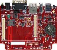
The TS-8200 is a TS-SOCKET Baseboard that provides a test and development platform for Technologic Systems TS-4xxx products. and accepts any TS-4xxx Macrocontroller. The TS-8200 provides industry standard connectors for the various ports and features on many of the TS Macrocontroller products like the TS-4500, TS-4200, etc. It provides transceivers for the RS-232 ports, CAN port, and the RS-485 port, brought out to the male DB9 and .1" pitch header connections. It also has the Ethernet "magnetics", RJ-45 connector, USB Host and Device connectors, Temperature Sensor, MicroSD card socket, Realtime Clock Battery, and two LEDs. Power input requirement is regulated 5.0 to 12.0 VDC.
Getting Started
The TS-8200 board has no specific boot sequence since the processor and Linux Operating System are located on the selected TS-4000 Series Macrocontroller. For the rest of the boot and setup procedure, please refer to the manual for the selected TS-4000 series Macrocontroller you are using listed here.
Before attempting to apply power to the TS-8200, perform the following steps while taking proper static discharge precautions
- Place the TS-8200 base board on a firm non-conductive surface.
- Carefully, insert the TS-4000 Series Macrocontroller daughterboard by aligning and pressing evenly and firmly onto the pair of mating connectors
- Connect the console serial terminal cable
- Connect the Ethernet cable is applicable.
- Apply power
- Monitor the TS-SOCKET SBC using a terminal emulator connected to the serial console port to verify that the board is operating properly
- Connect either a regulated 5.0 to 12.0 VDC on the power input connector or the regulated 5.0 VDC via USB Device port. Please note the polarity printed on the board.
Common Connectors
Push Switch
The TS-8200 contains a push switch that has multiple functions. On unit reset (or power on) the switch connects to a simple DIO input where the state of the switch may be read. The initial startup software may branch and perform any required functionality based on the switch state. The switch may also be deployed as a reset button, by setting an enable bit within the FPGA. This is the default behavior of the boot sequence, enabling the switch as a reset button approximately 1 second after reset or power on.
Ethernet
The TS-8200 contains a single Ethernet port interface utilizing an MMT MJKF4602 RJ-45 jack with integrated magnetic's and both Link Activity and Speed LED's. The LINK LED (right side of connector, green) is active when a valid Ethernet link is detected. This LED should be ON whenever the TS-8200 is powered and properly connected to a 10/100 BaseT Ethernet network.
MicroSD Interface
This MicroSD is on the same lines as the MicroSD on the macrocontroller. Only one ca be populated at the same time.
Macrocontroller Specific Connectors
TS-4200
Temperature Sensor
See the ts4200ctl for usage and sources for interacting with the temperature sensor.
DB9
| DB9 Pin | TS-Socket Location | Name | Macrocontroller Usage |
|---|---|---|---|
| 1 | CN2 78 / CN2 80 | PB4 / PB5 | RS485+ on ttyS1 |
| 2 | CN2 95 | DEBUG_RXD | RS232 Console RXD on ttyS0 |
| 3 | CN2 93 | DEBUG_TXD | RS232 Console TXD on ttyS0 |
| 4 | CN2 97 / CN2 99 | CAN_H | Reserved |
| 5 | GND | Ground | N/A |
| 6 | CN2 78 / CN2 80 | PB4 / PB5 | RS485- on ttyS1 |
| 7 | CN2 82 | PB6 | RS232 serial TXD for ttyS2 |
| 8 | CN2 84 | PB7 | RS232 serial RXD for ttyS2 |
| 9 | CN2 97 / CN2 99 | CAN_L | Reserved |
USB0
This is brought out as a USB 2.0 host.
USB 1
This is brought out as a USB 2.0 host.
USB DEV
The TS-4200 CPU supports USB Device.
