TS-7100
| WARNING: | This product is about to enter the Engineering Sampling program. This means the documentation and product itself may change several times before the product is deemed ready for large quantity orders. Please force-refresh (shift-f5 or ⌘-shift-R on most browsers) to clear your cache when visiting this page to ensure you are viewing the most recent version of this documentation. Of course also please check back often as this information is subject to change. |
 | |
| Product Page | |
| Specifications | |
| Documentation | |
|---|---|
| Schematic | |
| FTP Path | |
| Processor | |
| NXP i.MX6UL | |
| 696 MHz Arm® Cortex®-A7 | |
| i.MX6UL Product Page | |
| CPU Documentation |
About This Manual
The TS-7100 series of products all incorporate two PCBs connected by a high density connector. One of these PCBs contains the CPU and some basic peripherals. The second PCB is considered to be the "I/O board" which breaks out GPIO, networking, as well as other peripherals that can vary from product to product. Every product in the TS-7100 series uses the same CPU board and offers the same base features. All of the TS-7100 series products will have a full product number, for example "TS-7100-Z" is the first product in this line. This manual and all TS-7100 series product manuals will both use "TS-7100" as well as the full product number.
When the "TS-7100" name is used, this indicates that this feature is common to all products in the series. For example, soldered down eMMC flash is soldered to the CPU board. When the full product number is used, it is used to indicate that the feature or peripheral being discussed is available on that product, but not necessarily every product in the TS-7100 series.
As always, if there are any questions or concerns, please reach out to Technologic Systems' support team.
Overview
The TS-7100 is a small embedded CPU module with a 696 MHz NXP i.MX6UL CPU. The CPU module provides DDR3 RAM, soldered-down eMMC flash, 2KiB of non-volatile FRAM storage, support for a 16-bit 240x320 resistive-touch LCD display, and many more standard features.
Configuration flexibility can be achieved via the TS-7100's mated I/O board. The I/O board provides industrial-rated connectors and peripherals such as Ethernet, CAN, UARTs, WiFi and Bluetooth to expand functionality and interact with the real world.
The TS-7100-Z is the TS-7100 mated with the TS-7100-Z I/O board. The TS-7100-Z offers a DIN rail mountable enclosure with LCD and touch screen display, as well as wireless connectivity and industrial I/O. Peripherals available on the TS-7100-Z board include: soldered down WiFi with built in Bluetooth, our TS-SILO supercapacitor technology for safe shutdown upon power loss, dual 10/100 Ethernet ports, two relays, dual USB host ports, 30 VDC high-current low-side switch outputs or digital inputs, dedicated 30 VDC digital inputs, dedicated high-side switch output, 0-12 V or 4-20 mA ADC inputs, with all I/O protected by a hardware over-voltage or over-current breaker system, and a 8 V to 48 V DC input range.
Getting Started
A Linux PC is recommended for development, and will be assumed for this documentation. For users in Windows or OSX we recommend virtualizing a Linux PC. Most of our platforms run Debian and if there is no personal distribution preference this is what we recommend for ease of use.
Virtualization
Suggested Linux Distributions
It may be possible to develop using a Windows or OSX system, but this is not supported. Development will include accessing drives formatted for Linux and often Linux based tools.
Connect USB Console
The TS-7100 includes a USB Micro B device port; this uses a 8051 based microcontroller to create a debug/console serial interface on a host PC. The serial console is provided through this port at 115200 baud, 8n1, with no flow control. The USB serial device is a CP210x Virtual COM Port. Most operating systems have built-in support for this device. If not however, drivers are available for the device here.
Console from Linux
There are many serial terminal applications for Linux, three common used applications are picocom, screen, and minicom. These examples demonstrate all three applications and assume that the serial device is "/dev/ttyUSB0" which is common for USB adapters. Be sure to replace the serial device string with that of the device on your workstation.
picocom is a very small and simple client.
sudo picocom -b 115200 /dev/ttyUSB0
screen is a terminal multiplexer which happens to have serial support.
sudo screen /dev/ttyUSB0 115200
Or a very commonly used client is minicom which is quite powerful but requires some setup:
sudo minicom -s
- Navigate to 'serial port setup'
- Type "a" and change location of serial device to "/dev/ttyUSB0" then hit "enter"
- If needed, modify the settings to match this and hit "esc" when done:
     E - Bps/Par/Bits          : 115200 8N1
     F - Hardware Flow Control : No
     G - Software Flow Control : No
- Navigate to 'Save setup as dfl', hit "enter", and then "esc"
Console from Windows
Putty is a small simple client available for download here. Open up Device Manager to determine your console port. See the putty configuration image for more details.


Powering Up
| WARNING: | Be sure to take appropriate Electrostatic Discharge (ESD) precautions. Disconnect the power source before moving, cabling, or performing any set up procedures. Inappropriate handling may cause damage to the board. |
Power input to the TS-7100 is supplied via the power input connector, refer to that section for information on voltage ranges for this device.
Once power is applied to the whole device, there will be output on the debug console port. The following section of the manual provides information on getting the serial console connected.
U-Boot 2016.03-00408-gd450758c91 (Oct 10 2019 - 11:59:08 -0700)

CPU:   Freescale i.MX6UL rev1.2 at 396 MHz
Reset cause: POR
I2C:   ready
DRAM:  512 MiB
MMC:   FSL_SDHC: 0
Net:   FEC0 [PRIME]
Warning: FEC0 (eth0) using random MAC address - 72:12:64:ca:3e:4a

Press Ctrl+C to abort autoboot in 1 second(s)
starting USB...
USB0:   Port not available.
USB1:   USB EHCI 1.00
scanning bus 1 for devices... 1 USB Device(s) found
       scanning usb for storage devices... 0 Storage Device(s) found
No storage devices, perhaps not 'usb start'ed..?
Booting from the eMMC ...
** File not found /boot/boot.ub **
31526 bytes read in 103 ms (298.8 KiB/s)
5253608 bytes read in 354 ms (14.2 MiB/s)
NO CHRG jumper is set, not waiting

Kernel image @ 0x80800000 [ 0x000000 - 0x500220 ]
root ## Flattened Device Tree blob at 83000000
   Booting using the fdt blob at 0x83000000
   Using Device Tree in place at 83000000, end 8300a909

Starting kernel ...
| Note: | The "*** Warning - bad CRC, using default environment" message can be safely ignored when the unit is first booted. This means that no environment variables have been saved to disk, and U-Boot is falling back to the default. If "env save" is run, this will save the environment to disk, and this message will go away unless there is a further issue. |
The default U-Boot boot process will check for USB updates before attempting to boot from on-board eMMC. Details about the bootup process, features, and other U-Boot information can be found in the U-Boot sections.
First Linux Boot
When booting with the default settings, a shipped board will boot to the eMMC. The eMMC by default is pre-programmed with a Debian 10 Buster image. After Debian boots it will ask the user to log in with a username and password. Use "root" as the username with no password. After logging in, a password can be set with the passwd command. Note that this login will only work over the serial console. Debian SSH defaults to not only disallowing un-credentialed logins, but denying root logins altogether.
From the Linux prompt, the hardware can be tested out or application development can begin.
U-Boot
Debian 10
Debian is a community run Linux distribution. Debian provides tens of thousands of precompiled applications and services. This distribution is known for stability and large community providing support and documentation. The installation is specific to our board, but most Debian documentation applies:
Debian 10 - Getting Started
Once installed, the default user is "root" with no password.
This image can be written to a USB drive, or to the eMMC. For development, a USB thumbdrive will be simplest. If a bootable USB drive is connected this will take priority over other boot media. Plug in a USB drive and check the last output from "dmesg" to get the USB disk. For example, this may be /dev/sdc.
# Erase all older partitions
sudo sgdisk --zap-all /dev/sdc
# Create one GPT Linux partition
sudo sgdisk -n 0:0:0 -t 0:8300 /dev/sdc
# Create a filesystem and mount
sudo mkfs.ext4 /dev/sdc1
sudo mkdir /mnt/usb/
sudo mount /dev/sdc1 /mnt/usb/
# Extract downloaded image:
sudo tar --numeric-owner -xf tsimx6ul-debian-buster-latest.tar.xz -C /mnt/usb/
sudo chmod 755 /mnt/usb/
sudo umount /mnt/usb/
These commands will also work while booted from a USB drive to rewrite the eMMC. Instead of /dev/sdc you would use /dev/mmcblk0, and instead of /dev/sdc1 you would use /dev/mmcblk0p1.
Debian 10 - Configuring the Network
| Note: | See the section on Ethernet Ports for port details specific to your TS-7100 model. |
Ethernet
A file with the name of each network device to be configured is placed in /etc/network/interfaces.d/. The example below demonstrates configuration and use of the wired Ethernet device 'eth0'. For complete documentation, see Debian's documentation here
Some common examples are shown below.
DHCP on eth0:
cat > /etc/network/interfaces.d/eth0 <<EOF
auto eth0
allow-hotplug eth0
iface eth0 inet dhcp
EOF
Static IP on eth0:
cat > /etc/network/interfaces.d/eth0 <<EOF
auto eth0
iface eth0 inet static
    address 192.0.2.7/24
    gateway 192.0.2.254
EOF
The network can then be brought up with the command:
ifup eth0
Wi-Fi Client
| Note: | The latest image for this platform as of April 28th, 2022 has known issues with the Wi-Fi driver due to incompatibility with cfg80211 powersave modes.
If using Wi-Fi, it is strongly recommended to bring up the Wi-Fi interface, and then run This issue will be addressed in future images and has already been addressed in our kernel sources. We will continue to provide updates as we receive them from the Wi-Fi module manufacturer. |
If connecting to a WPA/WPA2 network, a wpa_supplicant config file must first be created:
wpa_passphrase yournetwork yournetworkpassphrase > /etc/wpa_supplicant/wpa_supplicant-wlan0.conf
Create the file /lib/systemd/system/wpa_supplicant@.service with these contents
[Unit]
Description=WPA supplicant daemon (interface-specific version)
Requires=sys-subsystem-net-devices-%i.device
After=sys-subsystem-net-devices-%i.device

[Service]
Type=simple
ExecStart=/sbin/wpa_supplicant -c/etc/wpa_supplicant/wpa_supplicant-%I.conf -i%I

[Install]
Alias=multi-user.target.wants/wpa_supplicant@%i.service
Create the file /etc/systemd/network/wlan0.network with:
[Match]
Name=wlan0

[Network]
DHCP=yes
See the systemctl-networkd example for setting a static IP for a network interface. The wlan0.network can be configured the same way as an eth.network.
To enable all of the changes that have been made, run the following commands:
systemctl enable wpa_supplicant@wlan0
systemctl start wpa_supplicant@wlan0
systemctl restart systemd-networkd
Host a Wi-Fi Access Point
| Note: | The latest image for this platform as of April 28th, 2022 has known issues with the Wi-Fi driver due to incompatibility with cfg80211 powersave modes.
If using Wi-Fi, it is strongly recommended to bring up the Wi-Fi interface, and then run This issue will be addressed in future images and has already been addressed in our kernel sources. We will continue to provide updates as we receive them from the Wi-Fi module manufacturer. |
This section will discuss setting up the WiFi device as an access point that is bridged to an ethernet port. That is, clients can connect to the AP and will be connected to the ethernet network through this network bridge. The ethernet network must provide a DHCP server; this will be passed through the bridge to WiFi client devices as they connect.
It is also possible to run a DHCP client on the platform itself. In this case the hostapd.conf file needs to be set up without bridging and a DHCP server needs to be configured. Refer to Debian's documentation for more details on DHCP server configuration.
The 'hostapd' utility is used to manage the access point of the device. This is usually installed by default, but can be installed with:
apt-get update && apt-get install hostapd -y
| Note: | The install process may start an unconfigured 'hostapd' process. This process must be killed before moving forward. |
Modify the file "/etc/hostapd/hostapd.conf" to have the following lines:
ssid=YourWiFiName
wpa_passphrase=Somepassphrase
interface=wlan0
bridge=br0
auth_algs=3
channel=7
driver=nl80211
hw_mode=g
logger_stdout=-1
logger_stdout_level=2
max_num_sta=5
rsn_pairwise=CCMP
wpa=2
wpa_key_mgmt=WPA-PSK
wpa_pairwise=TKIP CCMP
| Note: | Refer to the kernel's hostapd documentation for more wireless configuration options. |
The access point can be started and tested by hand:
hostapd /etc/hostapd/hostapd.conf
Systemd auto-start with bridge to eth0
It is possible to configure the auto-start of 'hostapd' through systemd. The configuration outlined below will set up a bridge with "eth0", meaning the Wi-Fi connection is directly connected to the ethernet network. The ethernet network is required to have a DHCP server present and active on it to assign Wi-Fi clients an IP address. This setup will allow Wi-Fi clients access to the same network as the ethernet port, and the bridge interface will allow the platform itself to access the network.
Set up hostapd
First, create the file "/etc/systemd/system/hostapd_user.service" with the following contents:
[Unit]
Description=Hostapd IEEE 802.11 AP
Wants=network.target
Before=network.target
Before=network.service
After=sys-subsystem-net-devices-wlan0.device
After=sys-subsystem-net-devices-br0.device
BindsTo=sys-subsystem-net-devices-wlan0.device
BindsTo=sys-subsystem-net-devices-br0.device

[Service]
Type=forking
PIDFile=/run/hostapd.pid
ExecStart=/usr/sbin/hostapd /etc/hostapd/hostapd.conf -P /run/hostapd.pid -B

[Install]
WantedBy=multi-user.target
Then enable this in systemd:
systemctl enable hostapd_user.service
systemctl enable systemd-networkd
Set up bridging
Create the following files with the listed contents.
"/etc/systemd/network/br0.netdev"
[NetDev]
Name=br0
Kind=bridge
"/etc/systemd/network/br0.network"
[Match]
Name=br0

[Network]
DHCP=yes
"/etc/systemd/network/bridge.network"
[Match]
Name=eth0

[Network]
Bridge=br0
Wi-Fi Concurrent Client / Access Point
| Note: | The latest image for this platform as of April 28th, 2022 has known issues with the Wi-Fi driver due to incompatibility with cfg80211 powersave modes.
If using Wi-Fi, it is strongly recommended to bring up the Wi-Fi interface, and then run This issue will be addressed in future images and has already been addressed in our kernel sources. We will continue to provide updates as we receive them from the Wi-Fi module manufacturer. |
The Wi-Fi device on this platform supports concurrent operation of client and access point (STA and AP). Please see the "Wi-Fi Client" section above first to connect the Wi-Fi module, in STA mode, to an external AP. This demo showcases the Wi-Fi module starting its own AP mode via hostapd with a simple static IP address while also being concurrently connected to a separate AP.
The 'hostapd' utility is used to manage the access point of the device. This is usually installed by default, but can be installed with:
apt-get update && apt-get install hostapd -y
| Note: | The install process may start an unconfigured 'hostapd' process. This process must be killed before moving forward. |
Modify the file /etc/hostapd/hostapd.conf to have the following lines:
ssid=YourWiFiName
wpa_passphrase=Somepassphrase
interface=p2p0
auth_algs=3
channel=<channel>
driver=nl80211
hw_mode=g
logger_stdout=-1
logger_stdout_level=2
max_num_sta=5
rsn_pairwise=CCMP
wpa=2
wpa_key_mgmt=WPA-PSK
wpa_pairwise=TKIP CCMP
| Note: | The channel used for AP must match the channel the STA is using! Be sure to set 'channel=...' in the above file to a proper channel number. |
| Note: | Refer to the kernel's hostapd documentation for more wireless configuration options. |
In order for the concurrent modes to work, a separate virtual wireless device must first be created. Note that hostapd.conf above lists interface=p2p0, a second interface with this name must be created:
iw wlan0 interface add p2p0 type managed
The access point can then be started and tested by hand:
hostapd /etc/hostapd/hostapd.conf &
An IP address can be set to p2p0:
ifconfig p2p0 192.168.0.1
From this point, other Wi-Fi clients can connect to the SSID YourWiFiName with the WPA2 key Somepassphrase with a static IP in the range of 192.168.0.0/24, and will be able to access the platform at 192.168.0.1. More advanced configurations are also possible, including bridging, routing/NAT, or simply separate networks with the Wi-Fi module connecting to a network and hosting its own private network with DHCP.
Debian 10 - Installing New Software
Debian provides the apt-get system which allows management of pre-built applications. The apt tools require a network connection to the internet in order to automatically download and install new software. The update command will download a list of the current versions of pre-built packages.
apt-get update
A common example is installing Java runtime support for a system. Find the package name first with search, and then install it.
root@tsa38x:~# apt-cache search openjdk
default-jdk - Standard Java or Java compatible Development Kit
default-jdk-doc - Standard Java or Java compatible Development Kit (documentation)
default-jdk-headless - Standard Java or Java compatible Development Kit (headless)
default-jre - Standard Java or Java compatible Runtime
default-jre-headless - Standard Java or Java compatible Runtime (headless)
jtreg - Regression Test Harness for the OpenJDK platform
libreoffice - office productivity suite (metapackage)
openjdk-11-dbg - Java runtime based on OpenJDK (debugging symbols)
openjdk-11-demo - Java runtime based on OpenJDK (demos and examples)
openjdk-11-doc - OpenJDK Development Kit (JDK) documentation
openjdk-11-jdk - OpenJDK Development Kit (JDK)
openjdk-11-jdk-headless - OpenJDK Development Kit (JDK) (headless)
openjdk-11-jre - OpenJDK Java runtime, using Hotspot JIT
openjdk-11-jre-headless - OpenJDK Java runtime, using Hotspot JIT (headless)
openjdk-11-jre-zero - Alternative JVM for OpenJDK, using Zero
openjdk-11-source - OpenJDK Development Kit (JDK) source files
uwsgi-app-integration-plugins - plugins for integration of uWSGI and application
uwsgi-plugin-jvm-openjdk-11 - Java plugin for uWSGI (OpenJDK 11)
uwsgi-plugin-jwsgi-openjdk-11 - JWSGI plugin for uWSGI (OpenJDK 11)
uwsgi-plugin-ring-openjdk-11 - Closure/Ring plugin for uWSGI (OpenJDK 11)
uwsgi-plugin-servlet-openjdk-11 - JWSGI plugin for uWSGI (OpenJDK 11)
java-package - Utility for creating Java Debian packages
In this case, the wanted package will likely be the "openjdk-11-jre" package. Names of packages can be found on Debian's wiki pages or the packages site.
With the package name apt-get install can be used to install the prebuilt packages.
apt-get install openjdk-11-jre
# More than one package can be installed at a time.
apt-get install openjdk-11-jre nano vim mplayer
For more information on using apt-get refer to Debian's documentation here.
Debian 10 - Setting Up SSH
Openssh is installed in our default Debian image, but by default openssh does not permit root logins, and requires a password to be set. Additionally, a host key is required if one hasn't already been created on the target board. To allow remote root login:
sed --in-place 's/#PermitRootLogin prohibit-password/PermitRootLogin yes/' /etc/ssh/sshd_config
systemctl restart ssh.service
/bin/ls /etc/ssh/ssh_host*key >/dev/null 2>&1  || ssh-keygen -A
passwd root # Set any password
If you ssh to this system it will now support ssh as root.
Debian 10 - Starting Automatically
A systemd service can be created to start up headless applications. Create a file in /etc/systemd/system/yourapp.service
[Unit]
Description=Run an application on startup

[Service]
Type=simple
ExecStart=/usr/local/bin/your_app_or_script

[Install]
WantedBy=multi-user.target
If networking is a dependency add "After=network.target" in the Unit section. Once you have this file in place add it to startup with:
# Start the app on startup, but will not start it now
systemctl enable yourapp.service

# Start the app now, but doesn't change auto startup
systemctl start yourapp.service
| Note: | See the systemd documentation for in depth documentation on services. |
Debian 10 - Cross Compiling
Debian only provides their cross compiler for their distribution. Our examples will set up a chroot for Debian to use for development. If using Debian 10 Buster directly, or through a VM, the schroot commands and debootstrap can be skipped.
First install the host system dependencies to use schroot and debootstrap:
# Ubuntu/Debian
sudo apt-get install debootstrap schroot
# Fedora
sudo dnf install debootstrap schroot
# Centos/redhat
sudo yum install debootstrap schroot
Use debootstrap to install a base Debian 10 for your host.
# Generate Debian Buster rootfs
sudo debootstrap buster /opt/chroots/buster-armdev/ http://deb.debian.org/debian
Then configure schroot to enter this rootfs. Replace "youruser" with your linux username.
sudo tee /etc/schroot/chroot.d/buster-armdev <<'EOF' >/dev/null
[buster-armdev]
description=Debian Buster for ARM development
directory=/opt/chroots/buster-armdev/
root-users=youruser
users=youruser
type=directory
EOF
Log into this schroot and install the armhf development tools (Skip if running a native Debian Buster host):
schroot -c buster-armdev
This will change your PS1 variable to indicate that you are in the Debian root. For example:
mark@mark-desktop:~$ sudo schroot -c buster-armdev
(buster-armdev)root@mark-desktop:/home/mark#
Install Debian's development tools for armhf:
# This workaround is required for Debian Buster
rm /var/lib/dpkg/statoverride

dpkg --add-architecture armhf
apt-get update
apt-get install -y build-essential gcc-arm-linux-gnueabihf bc \
  lzop u-boot-tools libncursesw5-dev file wget
exit
At this point the Debian chroot is ready to compile armhf binaries. For example, create a hello world in your home folder at ~/Documents/hello.c
#include <stdio.h>
int main(){
    printf("Hello World\n");
}
To compile this, you can enter the schroot as a normal user:
schroot -c buster-armdev
Keep in mind that when this is run as a normal user it does not modify your prompt. This will look like any other prompt, but will use your Debian applications instead. You can verify this is Debian with:
mark@mark-desktop:~/Documents$ cat /etc/issue
Debian GNU/Linux 10 \n \l
While logged into this schroot, run:
arm-linux-gnueabihf-gcc hello.c -o hello
exit
From here you can check "file hello" to verify the binary type:
mark@mark-desktop:~/Documents$ file hello
hello: ELF 32-bit LSB pie executable, ARM, EABI5 version 1 (SYSV), dynamically linked, interpreter /lib/ld-linux-armhf.so.3, for GNU/Linux 3.2.0, BuildID[sha1]=8a8cee3341d3ef76ef6796f72d5722ae9d77c8ea, not stripped
This can also be used to develop against dynamic libraries from Debian. The armhf packages can be installed in the chroot. For example, to link against curl:
# Run as root to install dependencies
sudo schroot -c buster-armdev
apt-get install libcurl4-openssl-dev:armhf
exit
# Return to arm chroot as a normal user:
schroot -c buster-armdev
# Download curl's simple.c example
wget https://raw.githubusercontent.com/bagder/curl/master/docs/examples/simple.c
arm-linux-gnueabihf-gcc simple.c -o simple -lcurl
The "simple" binary is now built for armhf and links dynamically to curl.
Buildroot Configuration
The full-featured Debian image may be too cumbersome for some applications. Applications that require faster bootup time or a smaller root filesystem will benefit greatly from using a lighter distribution like Buildroot. Using Buildroot for generating images makes it easy to keep software up to date, both userspace and kernel. Additionally, the use of Buildroot allows for building full images completely from source, with semi-reproducable builds, and full software license reports.
To assist customers heading down this path, we maintain our own Buildroot br2-external tree. This tree includes upstream Buildroot as a submodule, which eases updating between Buildroot releases. See the Buildroot manual for more information on Buildroot and br2-external trees.
In order to provide an easy transition from a larger Linux distribution to Buildroot, we provide and maintain two levels of configurations:
- The base configuration for each device brings in hardware support to get the unit booted, but offers minimal software support and relies mostly on tools provided by BusyBox.
- An "extra packages" defconfig that can be merged in with any of the base configurations in order to provide many additional packages to create an environment that is more consistent with larger Linux distributions.
The larger Buildroot configuration averages about 10 seconds of boot time, much of which is spent on networking. The base configurations can reduce this time significantly.
Our Buildroot br2-external currently uses the linux-5.10.y branch of our Linux LTS kernel repository for the majority of its supported platforms.
| Note: | Note that our base configurations include that device's utilities package where possible. Normally, these utilities (e.g. tshwctl, tsmicroctl, etc.) list the git hash of the build source in the help output. However, due to the Buildroot process, the git hash in these utilities reflects the git hash of Buildroot-ts, NOT of the utilities repository. There is no way to work around this without building the utilities outside of Buildroot.
|
Installing Buildroot
We offer a pre-made filesystem tarball that is based on our default Buildroot configuration. Please contact technical support regarding access to it.
Using that tarball, it's possible to create a bootable eMMC for the TS-7100.
The default configuration was designed to be as close to our stock Debian distribution. This includes our ts7100-utils like tsmicroctl, our TS-SILO monitor daemon, drivers and firmware for the WiFi and Bluetooth module.
Building Buildroot
Buildroot is intended to be completely cross-compiled from a host Linux workstation. This process creates a cross-compiler which is then used to build all target applications, kernel, etc., and then output a bootable image / tarball. The following instructions will create a bootable image / tarball for the target system:
Clone the repository:
git clone --recurse-submodules https://github.com/embeddedTS/buildroot-ts.git
cd buildroot-ts/
| Note: | Support for the TS-7100 and TS-7250-V3 in Buildroot are provided by the same configuration files. |
Configure the build:
# The following command uses a Buildroot script to merge two config files.
# The extra_packages_defconfig includes more usual packages to match our stock images
./buildroot/support/kconfig/merge_config.sh technologic/configs/extra_packages_defconfig technologic/configs/ts7250v3_defconfig

# A smaller base image can be made with bare hardware support using:
# make ts7250v3_defconfig
At this point, the default configuration can be modified if desired:
make menuconfig
And finally, start the build process:
make
The Buildroot process can take a large amount of time to build depending on available system resources. Note that if any changes occur in the config file, it is recommended to clean the build tree and start the process over. Buildroot ccache is not enabled by default, but can be to help speed up repeated builds. See the Buildroot manual for more information about ccache and Buildroot.
Configuring the Network
| Note: | See the section on Ethernet Ports for port details specific to your TS-7100 model. |
Buildroot implements the ip, ifconfig, route, etc., commands to manipulate the settings of interfaces. The first Ethernet interface is set up to come up automatically with our default configuration. The interfaces can also be manually set up:
# Bring up the CPU network interface
ifconfig eth0 up

# Set an IP address (assumes 255.255.255.0 subnet mask)
ifconfig eth0 192.168.0.50

# Set a specific subnet
ifconfig eth0 192.168.0.50 netmask 255.255.0.0

# Configure a default route. This is the server that provides an internet connection.
route add default gw 192.168.0.1

# Edit /etc/resolv.conf for the local DNS server
echo "nameserver 192.168.0.1" > /etc/resolv.conf
Most commonly, networks will offer DHCP which can be set up with one command:
# To setup the default CPU Ethernet port
udhcpc -i eth0
# All Ethernet ports can be made active and request DHCP addresses with:
udhcpc
To have network settings take effect on startup in Buildroot, edit /etc/network/interfaces:
# interface file auto-generated by Buildroot

auto lo
iface lo inet loopback

auto eth0
iface eth0 inet dhcp
  pre-up /etc/network/nfs_check
  wait-delay 15
Note that the default network startup may timeout on some networks, e.g. network protocols such as STP can delay packet movement. This can be resolved in Buildroot by adding network configuration options to fail after a number of attempts (rather than a timeout) or retry for a DHCP lease indefinitely. For example, adding one of the following lines under the iface eth0 inet dhcp section:
udhcpc_opts -t 0to infinitely retryudhcpc_opts -t 5to fail after five attempts.
See the man page for interfaces(5) for further information on the syntax of the interfaces file and all of the options that can be passed.
For more information on network configuration in general, Debian provides a great resource here that can be readily applied to Buildroot in most cases.
Installing New Software
Buildroot does not include a package manager by default (though it is possible to enable one). This means installing software directly on the platform can be cumbersome and is not the intended path when using Buildroot. It is recommended to modify the Buildroot configuration to include additional packages. See the Building Buildroot section for information on modifying the configuration to build additional packages.
If a desired package is not available in Buildroot, there are a number of options available moving forward. It is possible to add packages to the build process, though this does require some knowledge of Buildroot internals. Another option is to use the cross compiler that is output by Buildroot in order to compile packages on a host system and then copy them over to the target. It is also possible to install a toolchain directly on the device, and compile applications natively. The last option is the least recommended as it greatly increases the final image size and adds unnecessary complexity.
Setting up SSH
The default configuration has Dropbear set up. Dropbear is a lightweight SSH server.
Make sure the device is configured on the network and set a password for the remote user. SSH will not allow remote connections without a password set. The default configuration does not set a password for the root user, nor are any other users configured.
passwd root
After this setup it is now possible to connect from a remote PC supporting SSH. On Linux/OS X this is the ssh command, or from Windows using a client such as PuTTY.
Starting Automatically
Buildroot defaults to using the BusyBox init system, and all of our provided configurations use this as well. The following custom startup script uses this format. For information on other init systems that Buildroot can use, as well as creating startup scripts for these, see the Buildroot manual.
The most straightforward way to add an application to startup is to create a startup script. This example startup script that will toggle the red LED on during startup, and off during shutdown. In this case the script is named customstartup which can be changed as needed.
Create the file /etc/init.d/S99customstartup with the following contents. Be sure to set the script as executable!
#! /bin/sh
# /etc/init.d/customstartup

case "$1" in
  start)
    echo 1 > /sys/class/leds/red-led/brightness
    ## If you are launching a daemon or other long running processes
    ## this should be started with
    # nohup /usr/local/bin/yourdaemon &
    ;;
  stop)
    # if you have anything that needs to run on shutdown
    echo 0 > /sys/class/leds/red-led/brightness
    ;;
  *)
    echo "Usage: customstartup start|stop" >&2
    exit 3
    ;;
esac

exit 0
| Note: | The $PATH variable is not set up by default in init scripts so this will either need to be done manually or the full path to your application must be included. |
Buildroot provides numerous mechanisms to create this file in the target filesystem at build time. See the Buildroot manual for more information on this.
This script will be automatically called at startup and shutdown thanks to the file location and naming. However, it can also be manually started or stopped:
/etc/init.d/S99customstartup start
/etc/init.d/S99customstartup stop
Backup / Restore
While all of our products ship with images pre-loaded in to any supplied media, there are many situations where new images may need to be written. For example, to restore a device to its factory settings or apply a customized image/filesystem for application deployment. Additionally, specific units may be used for development and that unit's disk images need to be replicated to other units to be deployed in the field.
We offer a number of different ways to accomplish both capturing images to be written to other units, and the actual writing process itself. See the sections below for details on our USB Image Replicator tool to capture and/or write images, as well as details on manual processes to capture and write images on each of this device's media.
Image Replicator
This platform supports our Image Replicator tool. The Image Replicator tool is intended for use by developers as a means to write bootable images or filesystems on to a device's media (SD / eMMC / SATA / etc.) as part of their production or preparation process. In addition to writing media, the Image Replicator tool is capable of capturing images from a device's media and preparing them to be written to other devices.
The Image Replicator tool is a USB disk image that can be booted on a target device to capture or write its media directly without the need for a host workstation. The USB disk image is based on Buildroot and contains a set of scripts which handle the capture and write process. The process and its scripts are flexible and can be used as-is or adapted in to larger production processes to format and load data on to devices. The single USB drive can be used to capture images from a device, and then can be inserted in to other devices to write those same images on to other devices. The capture process is not necessary if it is not needed. Images for the target device can be copied to the USB drive, booted on compatible units, and have the target images written to that unit's media.
Image Capture Process
The image capture process performs the following steps. For more detailed information, see the Image Capture section below.
- If no valid images exist on the disk, image capture starts.
- For each valid media present on the unit, a bit for bit copy of the source is made.
- This image is mounted, sanitized (to remove unneeded files and allow safe copying of the image to other units), and saved as either a disk image or a tarball depending on the partition layout of the source disk.
- All images and tarballs are compressed, with both the output files having their MD5 hash saved as well as all of the files contained in the root partition having their MD5 hashes saved to a file for later verification.
The captured images and tarballs are named such that the USB Image Replicator disk can be immediately used to boot another unit and have it perform the Image Write process to write that unit's media with the captured images.
| Note: | When using this process, the USB drive used for the Image Replicator must be sized large enough to handle multiple compressed images as well as the uncompressed copy of the media image actively being worked with. If the image capture process runs out of space, the process will indicate a failure. |
Image Write Process
The image write process performs the following steps. For more details information see the Image Write section below.
- For each valid media present on the unit, find the first valid source image file for it.
- If a source image exists for a media that is not present on the unit, then the process indicates a failure.
- If the source image is a tarball, format the target disk with an appropriate filesystem, and unpack it to the target disk, verifying all files against the MD5 hash file list after they are written.
- If the source image is a disk image, write that to the target disk. If an MD5 file for the disk image exists, read back the written disk and compare it to the hash.
Creating a USB Image Replicator Disk
Image Replicator USB disk images can be found below:
Disk image: ts7100-usb-image-replicator.dd.xz
Tarball: ts7100-usb-image-replicator-rootfs.tar.xz
Two types of USB Image Replicator images are available for this platform, a tarball and an actual disk image. They both have the same contents and are intended to provide different methods to write the Image Replicator tool to a USB disk.
- Disk Image (.dd.xz)
- The disk image is easier to write from different workstation OSs, will auto-expand to the full disk length on its first boot, and is intended to be used for image capture (and later image writing) due to its small size and auto-expansion process. We recommend this route for users who may not have access to a Linux workstation or need to capture images from a golden unit first.
- Tarball Image (.tar.xz)
- The tarball image is easiest to write from a Linux workstation, but requires creating a partition table on the USB disk (if one does not already exist), formatting the filesystem, and unpacking the tarball. It can readily be used for for both image capture and writing, but is the easiest route when image capture is not needed due to the auto-expansion process.
| Note: | It is recommended to use USB drives with solid-state media for this process. Slower USB drives, especially those with spinning media, may take too long to enumerate and the bootloader will not boot the Image Replicator disk. Additionally, the use of low quality, damaged, and/or worn out USB drives may cause unexpected errors that appear unrelated to the USB drive itself. If there are issues using the Image Replicator, we recommend first trying a new, fresh, high-quality USB drive from a trusted named brand. |
Disk Image
This process uses a small disk image that can be written to a USB device. This disk image uses an ext3 filesystem which expands on its first boot to the full length of the disk before beginning the image capture process. This disk is recommended for users who may not have access to a Linux workstation or who need to capture images from a golden unit.
It is possible to use the disk image for just image writing, however, in order to ensure full disk space is available it is recommended to write the disk image to a USB drive, boot it on a unit, let the image capture process complete, insert the USB drive in to a workstation, and then remove the captured image files before copying in the desired image files for the target unit from the workstation.
Writing Disk Image From a Linux Workstation
The disk image can be written via the command line with the dd command (replace /dev/sdX with the correct USB device node):
xzcat <platform>-usb-image-replicator.dd.xz | dd of=/dev/sdX bs=1M conv=fsync
Graphical tools also exist for this purpose, for example balenaEtcher[1] offers this functionality.
Writing Disk Image From a Windows Workstation
A number of tools exist for writing an image to a USB drive, including (but not limited to) balenaEtcher[1] and Win32DiskImager[2]
Writing Disk Image From a MacOS Workstation
We recommend using a tool such as balenaEtcher[1] to write disk images.
Tarball
This process is easiest on a Linux workstation, but can be performs on other operating systems as well so long as they can support a compatible filesystem, the xz compression algorithm, as well as the tarball archive format. Note that in many cases, one of our computing platforms running our stock Linux image can be used if a Linux workstation is not available. After writing the tarball to a USB disk, the full length of the USB disk would be available to copy source images to in order to write them to other units.
The image replicator and scripts require a minimum of 50 MB; this plus the size of any target disk images or tarballs to be used dictates the minimum USB disk size required. The USB drive should have only a single partition, which is formatted ext2[1] / 3 / 4[2] or FAT32/vfat[3] Note that other filesystems are not compatible with U-Boot and therefore cannot be used.
Writing Tarball From a Linux Workstation
# This assumes USB drive is /dev/sdc:
sudo mkfs.ext3 /dev/sdc1
sudo mkdir /mnt/usb/
sudo mount /dev/sdc1 /mnt/usb/
sudo tar --numeric-owner -xf /path/to/<platform>-usb-image-replicator-rootfs.tar.xz -C /mnt/usb/
sudo umount /mnt/usb/
Writing Tarball From a Windows Workstation
It is recommended to use a third party tool, as native Windows archive tools have been observed to not work correctly. Tools such as 7-Zip[4] or PeaZip[5] are known working. It may also be possible to use Windows Subsystem for Linux following the Linux Workstation instructions above, but this has not been tested.
Note that some Windows tools may attempt to use the whole disk, rather than create a partition table. A partition table with a single partition is required for U-Boot support.
With a formatted USB disk, the archive can be unpacked to the root folder of the USB disk. Be sure to not unpack the tarball contents in to a new folder on the drive as this will not be bootable.
- ↑ The ext2 filesystem has a max file size limit as low at 16 GiB. This may cause issues for Image Capture.
- ↑ Use of ext4 may require additional options. U-Boot on some platforms does not support the 64-bit addressing added as the default behavior in recent revisions of
mkfs.ext4. If using e2fsprogs 1.43 or newer, the options-O ^64bit,^metadata_csummay need to be used with ext4 for proper compatibility. Older versions of e2fsprogs do not need these options passed, nor are they needed for ext2 / 3. - ↑ The FAT32 (supported by vfat in Linux) filesystem has a max file size limit of 4 GiB. This may cause issues for Image Capture.
- ↑ embeddedTS is not affiliated with this tool. 7-Zip 21.07 tested in Windows 10 on 20220222
- ↑ embeddedTS is not affiliated with this tool. PeaZip 7.2.0 tested in Windows 10 on 20220222
Running the Image Replicator Tool
Once a USB drive is formatted with the Image Replicator tool (see Creating a USB Image Replicator Disk for the correct files and process), boot to this USB drive (note that the Image Replicator already sets up the correct U-Boot boot scripts to boot to the USB drive, see the aforementioned section for details on how to make U-Boot call the scripts on the USB drive). This will start either image capture if no disk images/tarballs are present on the USB drive, or image write if there are disk images/tarballs present on the USB drive.
The Image Replicator tool, while in progress, will flash the green LED once per second while the red LED remains solidly lit. Upon completion, the red LED turns off and the green LED will slowly blink to indicate success, while a blinking red LED with the green LED off indicates a failure.
On each boot, startup scripts will check if the single partition of the USB drive can be expanded and do so if possible. If this process fails, then any further operations will not be run and the LEDs will blink to indicate a failure.
Image Capture
If no valid images to write exist on the booted USB Image Replicator drive, the image capture process starts automatically.
Note that while in progress, the USB Image Replicator drive is mounted read-write. It is not advised to remove power or disconnect the USB Image Replicator drive until the whole process has completed.
To help diagnose failures, files in /tmp/logs/ contain output from each capture process.
For each media present on the unit (SD / eMMC / SATA / etc.), the image capture process will do the following:
- Copy the entire media image to an appropriately named file on the USB Image Replicator drive, e.g.
sdimage.dd. No data is written to the source media and it is never mounted. The source disk can follow the stock partition layout, or implement a customized one. - Perform an fsck on the Linux rootfs partition in the image file. Note that, if deviating from the standard partition layout, it may be necessary to modify the scripts handling the capture process.
- Mount the Linux rootfs partition from the image file and sanitize the filesystem. The sanitization process removes temporary files (e.g.
/log/files), unique files (e.g. ssh private key files, machine ID files), adds a file to indicate that it is a custom image with the date as its contents, etc. The full list of operations can be found in this script. It may be necessary to modify this file for unique situations. - If the media's partition layout uses only a single partition, the filesystem is packed in to a tarball on the USB Image Replicator drive which is appropriately named and compressed, e.g.
sdimage.tar.xz. The image file is then unmounted and removed from the USB Image Replicator drive. - If the media's partition layout uses multiple partitions, the image file is then unmounted, an md5sum of the image file taken, it is compressed and appropriately named on the USB Image Replicator drive, e.g.
emmcimage.dd.xz, and then an md5sum of the compressed image is taken.
Note that when using this process, the USB Image Replicator drive that is used must be sized large enough to handle multiple compressed images as well as the uncompressed copy of the media image actively being worked with. If the image capture process runs out of space, the process will indicate a failure via the LEDs.
The images files captured are saved to the root folder of the USB Image Replicator drive. Upon completion, it is safe to remove power or unplug the USB drive.
For more details on the image capture process, see this script.
Image Write
This process is used to write existing images to media on a target unit. If appropriately named disk images or tarballs (see table below) are present in the root folder of the USB Image Replicator drive when booted, then the startup scripts will start the image writing process. The latest disk images we provide for our platforms can be downloaded from our FTP site, see the backup and restore section for links to these files.
Note that the USB Image Replicator drive remains read-only through the entire process but target devices may be mounted or actively written. It is not advised to remove power or disconnect the USB Image Replicator drive until the whole process has completed.
To help diagnose failures, files in /tmp/logs/ contain output from each writing process.
The Image Replicator script expects disk images or tarballs to have specific names to match the target media. The script will attempt to match tarball and then disk image names (in the order they are listed in the table below) for each target media, using the first file that is found to write to the target media. Note that symlinks can be used on the USB Image Replicator disk if formatted with a filesystem that supports symlinks. This can be used, for example, to write the same tarball to both SD and eMMC from only a single copy of the source tarball.
Upon completion, it is safe to remove power or unplug the USB drive.
For more details on the image write process, see this script.
The following table is the list of valid file names and how they are processed:
| Target media | Accepted filenames | Description |
|---|
| eMMC |
|
Tar of the filesystem. This will repartition the eMMC to a single partition and extract this tarball to the filesystem. If present, a file named /md5sums.txt in the tarball will have its contents checked against the whole filesystem after the tarball is extracted. This md5sums.txt file is optional and can be omitted, but it must not be blank if present. This file is present in our official images and is created during image capture with the Image Replicator tool.
|
|---|---|---|
|
|
Disk image of the media. This will be written to the eMMC block device directly. If present on the USB Image Replicator drive, a file named /emmcimage.dd.md5 will be used to verify the data written to the SD card against this checksum. This file is provided with our official images and is created during image capture with the Image Replicator tool.
|
| U-Boot |
|
U-Boot binary blob. This will be written to the bootloader area of eMMC. Note that both files are required for U-Boot, if either file is missing then the Image Replicator tool will not write either of them. If the file /SPL.md5 is present on the USB drive, this will be used to verify the data written to disk.
|
|---|
Building the Image Replicator from Source
The Image Replicator tool uses Buildroot to create the bootable USB disk image and tarball. See the project repository on github for information on compatibility and instructions on building: https://github.com/embeddedTS/buildroot-ts
Compile the Kernel
Compiling the kernel requires an armhf toolchain. We recommend development under Debian Stretch which includes an armhf compiler in the repositories. See the Debian Stretch cross compilation section for instructions on installing a proper cross compiler.
git clone https://github.com/embeddedTS/linux-4.9.y
cd linux-4.9.y

# These next commands set up some necessary environment variables
export ARCH=arm
export CROSS_COMPILE=arm-linux-gnueabihf-
export LOADADDR=0x80800000

# This sets up the default configuration that we ship with
make tsimx6ul_defconfig

## Make any changes in "make menuconfig" or driver modifications, then compile
make && make zImage && make modules
The following will install the kernel and modules to a temporary directory, and then pack them up in to a single tarball:
TEMPDIR=$(mktemp -d)
mkdir "${TEMPDIR}/boot/"
cp arch/arm/boot/zImage "${TEMPDIR}"/boot/zImage
cp arch/arm/boot/dts/imx6ul*ts*.dtb  "${TEMPDIR}"/boot/
INSTALL_MOD_PATH="${TEMPDIR}" make modules_install
INSTALL_HDR_PATH="${TEMPDIR}" make headers_install
tar czf linux-tsimx6ul-"$(cat include/config/kernel.release)"-"$(date +"%Y%m%d")".tar.gz -C "${TEMPDIR}" .
rm -rf "${TEMPDIR}"
This will output a tarball with the kernel version and short git hash, as well as the date the tarball was created. For example: linux-tsimx6ul-v4.9.171-60-g01e2117e-20190823.tar.gz
This tarball can be directly unpacked to the root folder of a bootable media for the device. It is also possible to unpack it directly on a booted system, however we do not recommend doing so on an active deployed system without extensive testing.
# Unpack it to a mounted disk, this assumes the disk is mounted to "/mnt"
tar xf linux-tsimx6ul...tar.gz -C /mnt

# Unpack it to the root directory of a booted system
tar xf linux-tsimx6ul...tar.gz -C /
Production Mechanism
The TS-7100's U-Boot has the ability to locate and run a U-Boot script file named /tsinit.ub on the root of a USB drive. This process occurs when attempting to boot to the U-Boot shell. If this script exists, U-Boot will load and run it automatically. This is intended for the initial production of units and allows mass programming various media from a USB mass storage device.
For access to the files described here, please contact technical support. This includes a basic Linux kernel and a small initramfs that will mount the USB drive at "/mnt/usb/" and execute "/mnt/usb/blast.sh".
The blast image and scripts require a minimum of 50 MB; this plus any disk images or tarballs used dictate the minimum disk size required. The USB drive must have at least 1 partition, with the first partition being formatted ext2/3 or fat32/vfat.
| Note: | The ext4 filesystem can be used instead of ext3, but it may require additional options. U-Boot does not support the 64bit addressing added as the default behavior in recent revisions of mkfs.ext4. If using e2fsprogs 1.43 or newer, the options "-O ^64bit,^metadata_csum" must be used with ext4 for proper compatibility. Older versions of e2fsprogs do not need these options passed nor are they needed for ext3. |
# This assumes USB drive is /dev/sdc:
sudo mkfs.ext3 /dev/sdc1
sudo mkdir /mnt/usb/
sudo mount /dev/sdc1 /mnt/usb/
sudo tar --numeric-owner -xf /path/to/tsimx6ul_usb_blaster-latest.tar.bz2 -C /mnt/usb/
At this point, disk images or tarballs would be copied to the /mnt/usb/ folder and named as noted below. The latest disk images we provide can be downloaded from our FTP site, see the backup and restore section for links to these files. Note that the script expects images and tarballs to have specific names. When using an ext* filesystem, symlinks can be used.
The formatted USB drive boots into a small Buildroot initramfs environment with filesystem and partitioning tools installed. This can be used to format SD, eMMC, or other disks. The Buildroot environment starts up and calls /blast.sh on the USB device. By default this script is set up to look for a number of of specific files on the USB disk and write these to media on the host device. Upon completion of the script the green or red LEDs will blink to visually indicate a pass or fail of the script. This script can be used without modification to write images from USB with these filenames:
| SD Card | sdimage.tar.{bz2,xz} | Tar of the filesystem. This will repartition the SD card to 1 ext4 partition and extract this tar to the filesystem. If present, a /md5sums.txt file will be checked and every file can be verified on the filesystem. This md5sums file is optional and can be omitted, but it must not be blank if present. |
|---|---|---|
| sdimage.dd.{bz2,xz} | Disk image of the card. This will be written to the SD card block device directly. If present, a sdimage.dd.md5 file be used to verify the data written to the SD card against this checksum. | |
| eMMC | emmcimage.tar.{bz2,xz} | Tar of the filesystem. This will repartition the eMMC to 1 ext4 partition and extract this tar to the filesystem. If present, a /md5sums.txt file will be checked and every file can be verified on the filesystem. This md5sums file is optional and can be omitted, but it must not be blank if present. |
| emmcimage.dd.{bz2,xz} | Disk image of the card. This will be written to mmcblk1 directly. If present, a emmcimage.dd.md5 file be used to verify the data written to the SD card against this checksum. |
Most users should be able to use the above script without modification. Our buildroot sources are available from our github repo. To build the whole setup and create a USB drive, the following commands can be used. See the repository README for information on the project and how to make modifications.
make tsimx6ul_usbprod_defconfig && make
The resulting output file tsimx6ul-usb-production-rootfs.tar.bz2 can be unpacked to the first partition of the USB drive as outlined above.
Features
ADC
The TS-7100-Z supports five 12-bit ADC inputs using the i.MX6UL CPU's integrated ADC. Four of these inputs can sample 0-12VDC or 0-20mA. The fifth can sample 0-50VDC.
The pin assignments and names for accessing each ADC input are:
| CN32 pin[1] | Pin label | Schematic name | CPU signal | 6UL GPIO | gpio-line-name | ADC | IIO name | Range |
|---|---|---|---|---|---|---|---|---|
| 27 | 4 | AN_0[2]
|
6UL_AN_0
|
GPIO1_IO04
|
AN_CH0
|
ADC1_IN4
|
voltage4 | 0-50 V |
| 25 | 5 | AN_1_STC
|
6UL_AN_1
|
GPIO1_IO05
|
AN_CH1
|
ADC1_IN5
|
voltage5 | 0-12 V |
| 23 | 8 | AN_2_STC
|
6UL_AN_2
|
GPIO1_IO08
|
AN_CH2
|
ADC1_IN8
|
voltage8 | 0-12 V |
| 21 | 9 | AN_3_STC
|
6UL_AN_3
|
GPIO1_IO09
|
AN_CH3
|
ADC1_IN9
|
voltage9 | 0-12 V |
| 19 | 0 | AN_4_STC
|
6UL_AN_4
|
GPIO1_IO00
|
AN_CH4
|
ADC1_IN0
|
voltage0 | 0-12 V |
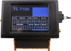
- ↑ See the TS-7100 IO Terminal Block section for a pinout illustration of the header, which is labeled CN32 on the schematic and silkscreen.
- ↑ The 0-50V
AN_0(Analog pin labeled 4) signal has an alternate function of being a high-side switch, as discussed in the GPIO section.
To switch an ADC to 0-20mA current-loop receiver mode, the appropriate enable must be set high. These are EN_CL_1 through EN_CL_4, and are controlled by GPIO commands as shown below.
| Pin label | Schematic Name | IIO Name | 0-12 V Select | 0-20 mA Loop Select | read-back[1] |
|---|---|---|---|---|---|
| 5 | AN_1_STC
|
voltage5 | gpioset $(gpiofind EN_CL_1)=0
|
gpioset $(gpiofind EN_CL_1)=1
|
gpioget $(gpiofind EN_ADC1_12V)
|
| 8 | AN_2_STC
|
voltage8 | gpioset $(gpiofind EN_CL_2)=0
|
gpioset $(gpiofind EN_CL_2)=1
|
gpioget $(gpiofind EN_ADC2_12V)
|
| 9 | AN_3_STC
|
voltage9 | gpioset $(gpiofind EN_CL_3)=0
|
gpioset $(gpiofind EN_CL_3)=1
|
gpioget $(gpiofind EN_ADC3_12V)
|
| 0 | AN_4_STC
|
voltage0 | gpioset $(gpiofind EN_CL_4)=0
|
gpioset $(gpiofind EN_CL_4)=1
|
gpioget $(gpiofind EN_ADC4_12V)
|
- ↑ The read-back sense is inverted from the write values, so reading 1 indicates that voltage is being sampled, and 0 indicates that current is being sampled.
| Note: | Only the four 0-12 V ADC inputs — corresponding with the pins labeled 5, 8, 9, and 0 in the above tables — can be used as current-loop receivers. |
IIO Access to ADCs
The preferred way to access these ADCs is through the Linux Industrial I/O Subsystem (IIO), which provides sample rates up to 6ksps across all inputs. The simplest API it offers for slow speed acquisition is via sysfs (/sys):
cat /sys/bus/iio/devices/iio:device0/in_voltage{4,5,8,9,0}_raw
The fastest API is in C which will get about 6ksps:
/* Build with gcc adc-test.c -o adc-test -liio
 * Gets ~6ksps
 * At the time of writing this does not support the buffer interface */

#include <stdint.h>
#include <stdio.h>
#include <string.h>
#include <assert.h>
#include <stdio.h>
#include <errno.h>
#include <iio.h>

uint32_t scale_mv(uint32_t raw, uint32_t max_mv)
{
	/* scale a 0-4095 raw reading to 0-max_mv mV */
	uint32_t val = raw * max_mv / 4095;

	return val;
}

int main(int argc, char **argv)
{
	static struct iio_context *ctx;
	static struct iio_device *dev;
	static struct iio_channel *chn[5];
	int i, ret;
	long long sample;

	ctx = iio_create_default_context();
	assert(ctx);
	dev = iio_context_find_device(ctx, "2198000.adc");
	assert(dev);

	chn[0] = iio_device_find_channel(dev, "voltage4", false);
	chn[1] = iio_device_find_channel(dev, "voltage5", false);
	chn[2] = iio_device_find_channel(dev, "voltage8", false);
	chn[3] = iio_device_find_channel(dev, "voltage9", false);
	chn[4] = iio_device_find_channel(dev, "voltage0", false);

	for (i = 0; i < 5; i++) {
		ret = iio_channel_attr_read_longlong(chn[i], "raw", &sample);
		assert(!ret);

		printf("AN_CH%d_mv=%d\n", i, scale_mv((uint32_t)sample, (i == 0) ? 50000 : 13325));
	}

	return 0;
}
The Python bindings currently achieve about 2ksps with similar code.
#!/usr/bin/env python

import iio

ctx = iio.Context('local:')
dev = ctx.find_device('2198000.adc')

scan_channels = ["voltage4", "voltage5", "voltage8", "voltage9", "voltage0"]

for chan_name in scan_channels:
	chan_n = int(chan_name[len("voltage"):])
	chn = dev.find_channel(chan_name)
	raw = int(chn.attrs['raw'].value)

	# Scale 0-4095 raw value to 0-12 V or 0-50 V for ADC 4.
	voltage_range = 50. if chan_n == 4 else 12.
	scaled = raw * voltage_range / 4095
	print('ADC1_IN{}={:.3f}'.format(chan_n, scaled))
Battery Backed RTC
The TS-7100 implements an STMicro "M41T00S" Battery Backed RTC using an external battery. This RTC is connected to the CPU via I2C and is handled by the kernel and is presented as a standard RTC device in Linux. On the TS-7100 series, the RTC is located on the CPU module with the battery backup located on the I/O board.
The TS-7100-Z I/O board provides battery-backed power to the RTC via a replaceable CR1632 coin cell.
Bluetooth
| Note: | The latest image for this platform as of April 28th, 2022 has known issues with the Wi-Fi driver and BLE coexistence due to incompatibility with cfg80211 powersave modes.
If using both Wi-Fi and BLE, it is strongly recommended to bring up the Wi-Fi interface, and then run This issue will be addressed in future images and has already been addressed in our kernel sources. We will continue to provide updates as we receive them from the Wi-Fi module manufacturer. |
The Wi-Fi option for this platform also includes a Bluetooth 5.0 LE module. Support for Bluetooth is provided by the BlueZ project. BlueZ has support for many different profiles for HID, A2DP, and many more. Refer to the BlueZ documentation for more information. Please see our BLE Examples page for information on installing the latest BlueZ release, getting started, and using demo applications.
Both Wi-Fi and Bluetooth can be active at the same time on this platform. Note however, that either the Wi-Fi interface needs to be not brought up if Wi-Fi is unused, or it needs to actively connect to an access point or act as an access point. The Bluetooth module can be activated with the following commands:
For Bluez versions found on Debian Stretch and below:
# Enable Bluetooth, and load the firmware
echo BT_POWER_UP > /dev/wilc_bt
sleep 1
echo BT_DOWNLOAD_FW > /dev/wilc_bt
sleep 1

# Attach the BLE device to the system, increase the baud, and enable flow control
hciattach /dev/ttymxc2 any 115200 noflow
sleep 1
hcitool cmd 0x3F 0x0053 00 10 0E 00 01
stty -F /dev/ttymxc2 921600 crtscts

# Note that no other HCI commands should be used! In older versions of BlueZ, HCI commands exist alongside bluetoothd, however HCI commands can interfere with the bluetoothd stack.
For newer versions of BlueZ found on Debian Buster or newer, or newer versions of BlueZ built from source:
echo BT_POWER_UP > /dev/wilc_bt
sleep 1
echo BT_DOWNLOAD_FW > /dev/wilc_bt
sleep 1

btattach -N -B /dev/ttymxc2 -S 115200 &
sleep 1
bluetoothctl power on
sleep 1
hcitool cmd 0x3F 0x0053 00 10 0E 00 01
kill %1 # This terminates the above btattach command
sleep 1
btattach -B /dev/ttymxc2 -S 921600 &
At this point, the device is running at 921600 baud with flow control, and is fully set up ready to be controlled by various components of BlueZ tools. For example, to do a scan of nearby devices:
bluetoothctl
power on
scan on
This will return a list of devices such as:
root@ts-imx6ul:~# bluetoothctl
Agent registered
[CHG] Controller F8:F0:05:XX:XX:XX Pairable: yes
[bluetooth]# power on
Changing power on succeeded
[CHG] Controller F8:F0:05:XX:XX:XX Powered: yes
[bluetooth]# scan on
Discovery started
[CHG] Controller F8:F0:05:XX:XX:XX Discovering: yes
[NEW] Device 51:DD:C0:XX:XX:XX Device_Name
[NEW] Device 2A:20:E2:XX:XX:XX Device_Name
[CHG] Device 51:DD:C0:XX:XX:XX RSSI: -93
[CHG] Device 51:DD:C0:XX:XX:XX RSSI: -82
[NEW] Device E2:08:B5:XX:XX:XX Device_Name
[CHG] Device 51:DD:C0:XX:XX:XX RSSI: -93
[CHG] Device 2A:20:E2:XX:XX:XX RSSI: -94
[NEW] Device 68:62:92:XX:XX:XX Device_Name
[NEW] Device 68:79:12:XX:XX:XX Device_Name
[bluetooth]# quit
Please note that the Bluetooth module requires the modem control lines CTS and RTS as flow control when running at higher baud rates. It is possible to run the module at the initial 115200 baud if the flow control lines are unwanted.
The module supports some other commands as well:
# Allow the BT chip to enter sleep mode
echo BT_FW_CHIP_ALLOW_SLEEP > /dev/wilc_bt

# Power down the BT radio when not in use
echo BT_POWER_DOWN > /dev/wilc_bt
CAN
The TS-7100-Z CPU has a single FlexCAN port that uses the Linux SocketCAN implementation. The port can be set up and used with the following command:
ip link set can0 up type can bitrate 1000000
The CAN transceiver is automatically controlled by the kernel. If the interface is brought up in Linux then the transceiver will be enabled. By default when the kernel boots, the interface is down, and therefore the transceiver is disabled.
At this point, the port can be used with standard SocketCAN libraries. In Debian, we provide the utilities 'cansend' and 'candump' to test the ports or as a simple packet send/receive tool. In order to test the port, tie CAN_H to the CAN_H pin of the bus, doing the same for the CAN_L pin. Then use the following commands:
candump can0
# This command will echo all data received on the bus to the terminal

cansend can0 7Df#03010c
#This command will send out the above CAN packet to the bus
The above example packet is designed to work with the Ozen Elektronik myOByDic 1610 ECU simulator to read the RPM speed. In this case, the ECU simulator would return data from candump with:
 <0x7e8> [8] 04 41 0c 60 40 00 00 00
 <0x7e9> [8] 04 41 0c 60 40 00 00 00
In the output above, columns 6 and 7 are the current RPM value. This shows a simple way to prove out the communication before moving to another language.
The following example sends the same packet and parses the same response in C:
#include <stdio.h>
#include <pthread.h>
#include <net/if.h>
#include <string.h>
#include <unistd.h>
#include <net/if.h>
#include <sys/ioctl.h>
#include <assert.h>
#include <linux/can.h>
#include <linux/can/raw.h>

int main(void)
{
	int s;
	int nbytes;
	struct sockaddr_can addr;
	struct can_frame frame;
	struct ifreq ifr;
	struct iovec iov;
	struct msghdr msg;
	char ctrlmsg[CMSG_SPACE(sizeof(struct timeval)) + CMSG_SPACE(sizeof(__u32))];
	char *ifname = "can0";

	if((s = socket(PF_CAN, SOCK_RAW, CAN_RAW)) < 0) {
		perror("Error while opening socket");
		return -1;
	}

	strcpy(ifr.ifr_name, ifname);
	ioctl(s, SIOCGIFINDEX, &ifr);
	addr.can_family  = AF_CAN;
	addr.can_ifindex = ifr.ifr_ifindex;

	if(bind(s, (struct sockaddr *)&addr, sizeof(addr)) < 0) {
		perror("socket");
		return -2;
	}

 	/* For the ozen myOByDic 1610 this requests the RPM guage */
	frame.can_id  = 0x7df;
	frame.can_dlc = 3;
	frame.data[0] = 3;
	frame.data[1] = 1;
	frame.data[2] = 0x0c;

	nbytes = write(s, &frame, sizeof(struct can_frame));
	if(nbytes < 0) {
		perror("write");
		return -3;
	}

	iov.iov_base = &frame;
	msg.msg_name = &addr;
	msg.msg_iov = &iov;
	msg.msg_iovlen = 1;
	msg.msg_control = &ctrlmsg;
	iov.iov_len = sizeof(frame);
	msg.msg_namelen = sizeof(struct sockaddr_can);
	msg.msg_controllen = sizeof(ctrlmsg);
	msg.msg_flags = 0;

	do {
		nbytes = recvmsg(s, &msg, 0);
		if (nbytes < 0) {
			perror("read");
			return -4;
		}

		if (nbytes < (int)sizeof(struct can_frame)) {
			fprintf(stderr, "read: incomplete CAN frame\n");
		}
	} while(nbytes == 0);

	if(frame.data[0] == 0x4)
		printf("RPM at %d of 255\n", frame.data[3]);

	return 0;
}
See the Kernel's CAN documentation here. Other languages have bindings to access CAN such as Python, Java using JNI.
In production use of CAN we also recommend setting a restart-ms for each active CAN port.
ip link set can0 type can restart-ms 100
This allows the CAN bus to automatically recover in the event of a bus-off condition.
CPU
This device uses the i.MX6UL CPU, running at 696 MHz, based upon a Cortex-A7 core and targeting low power consumption.
Refer to NXP's documentation for more detailed information on the i.MX6UL.
eMMC Interface
| Note: | This section is incomplete at this time. |
The i.MX6UL SD card controller supports the MMC specification, the TS-7100 includes a soldered down eMMC IC to provide on-board flash media.
Our default software image contains 2 partitions:
| Device | Contents |
|---|---|
| /dev/mmcblk0 | eMMC block device |
| /dev/mmcblk0boot0 | eMMC boot partition |
| /dev/mmcblk0boot1 | eMMC boot partition |
| /dev/mmcblk0p1 | Full Debian Linux partition |
This platform includes an eMMC device, a soldered down MMC flash device. Our off the shelf builds are 4 GB, but up to 64 GB are available for customized builds. The eMMC flash appears to Linux as an SD card at /dev/mmcblk0. The eMMC includes additional boot partitions that are used by U-Boot and are not affected by the eMMC partition table.
The eMMC module has a similar concern by default to SD cards in that they should not be powered down during a write/erase cycle. However, this eMMC module includes support for setting a fuse for a "Write Reliability" mode, and a "psuedo SLC (pSLC)" mode. With both of these enabled all writes will be atomic to 512 B and each NAND cell will be treated as a single layer rather than a multi-layer cell. If a sector is being written during a power loss, a block is guaranteed to have either the old or new data. Even in cases where the wrong data is present on the next boot, fsck is often able to deal with the older data being present in a 512 B block. The downsides to setting these modes are that it will reduce the overall write speed and halve the available space on the eMMC to roughly 1.759 GiB. Please note that even with these settings, Technologic Systems strongly recommends designing the end application to eliminate any situations where a power-loss event can occur while any disk is mounted as read/write. The TS-SILO option available on certain TS-7100 I/O boards can help to eliminate the dangerous situation.
The 'mmc-utils' package is used to enable these modes. The command is pre-installed on the latest image. Additionally we have created a script to safely enable the write reliability and pSLC modes. Since the U-Boot binary and environment reside on the eMMC, care must be taken to save the current state of the boot partitions, enable the modes, restore the boot partitions, and re-enable proper booting options. This script can be used in combination with the production mechanism scripting to complete these steps as part of an end application production process.
| WARNING: | Enabling these modes causes all data on the disk to become invalid and must be rewritten. Do not attempt to run the 'mmc' commands from the script individually, all steps in the script must occur as they are or the unit may be unable to boot. If there are any failures of the script, care must be taken to resolve any issues while the unit is still booted or it may fail to boot in the future. |
| Note: | Enabling these modes is a one-way operation, it is not possible to undo them once they are made. Because of this, setting these eMMC modes will invalidate Technologic Systems' return/replacement warranty on the unit. See the warranty section for more information on this. |
The 'emmc_reliability' script can be found in the TS-7100 utilities github repository.
The script must be run when boot from any media other than eMMC, such as NFS, or USB. No partition of the eMMC disk can be mounted when these commands are run. Doing so may result in corruption or inability for the unit to boot. Once the pSLC mode is enabled, all data on the disk will become invalid. This means the partition table will need to be re-created, the filesystems formatted, and all filesystem contents re-written to disk. This is why we recommend using this script in conjunction with the production mechanism scripting. The 'emmc_reliability' script can be run first, then the rest of the production script can create and format the partitions as well as write data to disk.
The script requires a single argument, the device node of the eMMC disk, and will output verbosely to stderr. Any specific errors will also be printed out on stderr.
Example usage:
./emmc_reliability /dev/mmcblk0
Upon successful run, the script will return 0. Any errors will return a positive code. See the script for detailed error code information.
Ethernet
The NXP processor implements two 10/100 ethernet controllers with support built into the Linux kernel.
Linux device "eth0" (labeled "ETH B" on the enclosure) maps to the controller ethernet@20b4000, and device "eth1" (labeled "ETH A" on the enclosure) to ethernet@2188000.
Standard Linux utilities such as ifconfig/ip can be used to control this interface. See the Configuring the Network section for more details. For the specifics of this interface see the CPU manual.
FEC PTP Support
The i.MX6UL CPU Ethernet supports 1588 PTP (PTPv1 & PTPv2).
PTP is supported in Linux via the linuxptp project. This allows synchronizing the system clock to within ±1 us.
Note that Linux kernel version 4.9 or greater is required for PTP support with the i.MX6UL CPU. An example of setting up an ethernet interface with PTP and adjusting the clock based on that is below.
apt-get install linuxptp -y

# For PTP on eth0
phc2sys -s /dev/ptp0 -w &
ptp4l -2 -H -i eth0 -m -p /dev/ptp0 &

# For PTP on eth1
phc2sys -s /dev/ptp1 -w &
ptp4l -2 -H -i eth1 -m -p /dev/ptp1 &
If the clocks are significantly off this may take time for the clocks to converge.
FPGA
FPGA Registers
The TS-7100 FPGA is connected to the CPU over the WEIM bus. This provides 8-bit, 16-bit, or 32-bit access to the FPGA mapped at 0x5000_0000.
For example, to read the FPGA information at the first register of the syscon:
root@ts-imx6ul:~# memtool md -l 0x50004000+4
50004000: 00000006
| Offset | Description |
|---|---|
| 0x0000 | UART 16550 #0 |
| 0x0100 | Opencore SPI controller #0 |
| 0x0120 | Opencore SPI controller #1 |
| 0x4000 | FPGA Syscon |
FPGA 16550
This FPGA includes a 16550 UART peripheral that can be used as a standard Linux serial port. It is not recommended to interact directly with these registers.
FPGA SPI
This FPGA includes a pair of SPI master devices. These are used for the FRAM memory, accessing the flash used for the LCD splash screen image, and the LCD touch screen itself. All of these operations are handled via the Linux kernel. It is not recommended to interact directly with these registers
FPGA Syscon
The FPGA syscon is the main system control block of the FPGA. Contained in this region is the FPGA GPIO, PWM, and IRQ control. It is not recommended to interact directly with these registers unless directed to do so by other manual sections.
Some registers are dual purpose, having separate read and write functionality; while others may only have write functionality. Registers that do not read and write the same are indicated with "(RD)" and "(WR)" notation. All other registers read and write the same data set. Any unlisted register addresses are Reserved / Undefined.
- ↑ Note that this is also used for UART clock generation.
FPGA IRQs
| Bit | Description |
|---|---|
| 31:17 | Reserved |
| 16 | Touch Screen IRQ |
| 15:13 | Reserved |
| 12 | DIO Fault Breaker IRQ |
| 11 | Reserved |
| 10 | Opencore SPI Controller #1 IRQ |
| 9 | Opencore SPI Controller #0 IRQ |
| 8:1 | Reserved |
| 0 | UART #0 IRQ |
FRAM
This platform supports a soldered-down, non-volatile Ferroelectric RAM (FRAM) device. The Cypress FM25L16B is a 2 KiB FRAM device in a configuration not unlike an SPI EEPROM. The nature of FRAM means it is non-volatile, incredibly fast to write, and is specified with 100 trillion read/write cycles (per each of the 256 sequential 8 byte rows) with a 150 year data retention at temperatures below 65 °C. The device is connected to Linux and presents itself as a flat file that can be read and written like any standard Linux file.
The FRAM can be accessed as a flat file from Linux:
# xxd -a /sys/bus/spi/devices/spi32766.0/eeprom | head
00000000: 0000 0000 0000 0000 0000 0000 0000 0000  ................
*
000007f0: 0000 0000 0000 0000 0000 0000 0000 0075  ...............u
If U-Boot's bootcount tracking environment variable is enabled, the last byte of FRAM is reserved for storing the boot count, and care should be taken to not overwrite it inadvertently. In U-Boot, the boot count can be accessed with the fram command.
GPIO
| Note: | This section is incomplete at this time. |
The i.MX6UL CPU and FPGA GPIOs are exposed using a kernel character device. This interface provides a set of files and directories for interacting with GPIO which can be used from any language that interact with special files in linux using ioctl() or similar. For our platforms, we pre-install the "libgpiod" library and binaries. Documentation on these tools can be found here. This section only covers using these userspace tools and does not provide guidance on using the libgpiod library in end applications. Please see the libgpiod documentation for this purpose.
A user with suitable permissions to read and write /dev/gpiochip* files can immediately interact with GPIO pins. For example, to see if input power has failed:
gpioget $(gpiofind POWER_FAIL_3V)
Multiple pins in the same chip can be read simultaneously by passing multiple pin numbers separated by spaces.
To write to a pin, the gpioset command is used. For example, to set Relay 1:
gpioset $(gpiofind EN_RELAY_1)=1
Multiple pins in the same chip can be set simultaneously by passing multiple pin=value pairs separated by spaces.
If a call with gpioset or gpioget fails with "Device or resource busy," that means that specific GPIO is claimed by another device. The command cat /sys/kernel/debug/gpio can be used to get a list of all of the system GPIO and what has claimed them.
The gpiomon tool can be used to monitor pins for changes to GPIOs that generate interrupts (i.e., CPU GPIOs).
In the following table, gpiochips 0, 3 and 4 are on the CPU, and gpiochips 5 through 7 are on the FPGA.
Because this numbering is subject to change, it is advisable to use the gpiofind command to look it up by its label, as shown in the usage examples above and elsewhere in this manual.
| Label | Chip | Pin | Location |
|---|---|---|---|
AN_CH4[1]
|
0 | 0 | AIN 4 or Digital Input AIN 4 on CN32 Terminal |
RTC_BATT_FAIL
|
0 | 1 | Battery failed/missing on the Battery Connector |
AN_CH0[1]
|
0 | 4 | AIN 0 on CN32 Terminal |
AN_CH1[1]
|
0 | 5 | AIN 1 or Digital Input AIN 1 on CN32 Terminal |
AN_CH2[1]
|
0 | 8 | AIN 2 or Digital Input AIN 2 on CN32 Terminal |
AN_CH3[1]
|
0 | 9 | AIN 3 or Digital Input AIN 3 on CN32 Terminal |
| 0 | 18 | CPU Board Red LED | |
| 0 | 19 | CPU Board Green LED | |
NIM_STATUS
|
3 | 14 | Pin 13 on CN16 (XBee/Nimbelink_Socket) |
POWER_FAIL_3V
|
4 | 0 | Power Input Failure |
FPGA_IRQ[1]
|
4 | 1 | FPGA Interrupt input pin |
EN_RELAY_1
|
4 | 4 | Relay 1 on CN32 Terminal |
EN_RELAY_2
|
4 | 5 | Relay 2 on CN32 Terminal |
NIM_RESET
|
4 | 6 | Pin 5 on CN16 (XBee/Nimbelink_Socket) |
DIO_1_OUT
|
5 | 0 | DIO 1 Out or PWM on CN32 Terminal |
DIO_2_OUT
|
5 | 1 | DIO 2 Out or PWM on CN32 Terminal |
DIO_1_IN
|
5 | 2 | DIO 1 In on CN32 Terminal |
DIO_2_IN
|
5 | 3 | DIO 2 In on CN32 Terminal |
DIO_3_IN
|
5 | 4 | DIO 3 In on CN32 Terminal |
DIO_6
|
5 | 5 | FPGA DIO 06 |
DIG_IN_1
|
5 | 6 | Digital In 1 on CN32 Terminal |
DIG_IN_2
|
5 | 7 | Digital In 2 on CN32 Terminal |
DIG_IN_3
|
5 | 8 | Digital In 3 on CN32 Terminal |
EN_CL_1
|
5 | 9 | AIN 1 4-20 mA current loop enable |
EN_CL_2
|
5 | 10 | AIN 2 4-20 mA current loop enable |
EN_CL_3
|
5 | 11 | AIN 3 4-20 mA current loop enable |
| 5 | 12 | Reserved | |
| 5 | 13 | Reserved | |
EN_CL_4
|
5 | 14 | AIN 4 4-20 mA current loop enable |
EN_HS_SW
|
5 | 15 | High-Side Switch or HSPWM |
EN_ADC1_12V
|
6 | 1 | AIN 1 0-12 V meas. mode [2] |
EN_ADC2_12V
|
6 | 2 | AIN 2 0-12 V meas. mode [2] |
EN_ADC3_12V
|
6 | 3 | AIN 3 0-12 V meas. mode [2] |
EN_ADC4_12V
|
6 | 4 | AIN 4 0-12 V meas. mode [2] |
EN_USB_HOST_5V
|
6 | 5 | en usb host 5v |
PHY_RESET#[1]
|
6 | 6 | Ethernet PHY reset |
WIFI_RESET#[1]
|
6 | 7 | WiFi module reset |
IO_RED_LED#[1]
|
6 | 8 | I/O Board Red LED |
IO_GREEN_LED#[1]
|
6 | 9 | I/O Board Green LED |
| 6 | 12 | Reserved | |
DIO_3_OUT
|
6 | 13 | DIO 3 Out or PWM on CN32 Terminal |
EN_HSPWM
|
6 | 14 | Enable high-side PWM |
EN_LSPWM
|
6 | 15 | Low-side PWM drain enable |
CPU_TOUCH_IRQ#[1]
|
7 | 0 | Touchscreen IRQ |
| 7 | 2 | FPGA Strapping Pin | |
| 7 | 3 | FPGA Strapping Pin | |
| 7 | 4 | FPGA Strapping Pin | |
| 7 | 5 | FPGA Strapping Pin | |
NIM_3V3#_4V
|
7 | 6 | Data 0: Select 3.3 V power on CN16 XBee Socket [3] |
| Data 1: Select 4 V power on CN16 XBee Socket [3] | |||
NIM_PWR_ON
|
7 | 8 | Pin 20 (Power Button) on CN16 XBee Socket |
SEL_NIM_USB
|
7 | 9 | Enable USB interface on CN16 XBee Socket [4] |
DIO_FAULT#
|
7 | 10 | I/O over-current/over-voltage breaker tripped [5] |
| 7 | 11 | FPGA Strapping Pin | |
| 7 | 12 | FPGA Strapping Pin | |
| 7 | 13 | Reserved | |
EN_BK_LT#[1]
|
7 | 14 | LCD backlight enable |
- ↑ 1.00 1.01 1.02 1.03 1.04 1.05 1.06 1.07 1.08 1.09 1.10 1.11 Claimed by driver. Not available for use.
- ↑ 2.0 2.1 2.2 2.3 This bit is read only. Clearing the associated current loop enable bit will set this bit, setting the CL enable will clear this bit
- ↑ 3.0 3.1 To disable power on this pin, set the GPIO as an input with 'gpioset' or otherwise
- ↑ This will relocate the USB channel connected to the top USB host port
- ↑ This bit must be cleared manually after a trip to de-assert the associated IRQ
Digital Inputs
The digital inputs on the TS-7100-Z are capable of supporting various voltage ranges and input modes. The digital inputs support dry contact switches as well as a driven input voltage. The table below lists each digital input, the bank and pin number for reading the input, the maximum input voltage range, the threshold voltages, as well as the location of the input. VIH Min is the minimum voltage on the input to trigger a logic 1 input. VIL Max is the maximum voltage on the input to trigger a logic 0 input. All of the digital inputs are hysteretic. The driving input must be able to at least sink current to drive the input low, but all digital inputs are compatible with push-pull drivers.
| Input Name | Bank | Pin | V Range | VIH Min | VIL Max | Location |
|---|---|---|---|---|---|---|
| Digital In 1 | 5 | 6 | 0-30 V | ~2.57 V | ~0.95 V | CN32 Terminal, pin 9 |
| Digital In 2 | 5 | 7 | 0-30 V | ~2.57 V | ~0.95 V | CN32 Terminal, pin 11 |
| Digital In 3 | 5 | 8 | 0-30 V | ~2.57 V | ~0.95 V | CN32 Terminal, pin 13 |
| DIO 1 In [1] | 5 | 2 | 0-30 V | ~2.54 V | ~0.90 V | CN32 Terminal, pin 14 |
| DIO 2 In [1] | 5 | 3 | 0-30 V | ~2.54 V | ~0.90 V | CN32 Terminal, pin 16 |
| DIO 3 In [1] | 5 | 4 | 0-30 V | ~2.54 V | ~0.90 V | CN32 Terminal, pin 18 |
| AIN 1 In [2] | 0 | 5 | 0-12 V | ~8.60 V | ~7.90 V | CN32 Terminal, pin 25 |
| AIN 2 In [2] | 0 | 8 | 0-12 V | ~8.60 V | ~7.90 V | CN32 Terminal, pin 23 |
| AIN 3 In [2] | 0 | 9 | 0-12 V | ~8.60 V | ~7.90 V | CN32 Terminal, pin 21 |
| AIN 4 In [2] | 0 | 0 | 0-12 V | ~8.60 V | ~7.90 V | CN32 Terminal, pin 19 |
- ↑ 1.0 1.1 1.2 This GPIO should only be read as an input. Its value reflects the voltage on the physical CN32 pin, regardless of output status
- ↑ 2.0 2.1 2.2 2.3 The AIN pins can be used as Digital Inputs, but require software changes first. See the ADC section for more information
Digital Outputs
The TS-7100-Z supports a handful of digital output pins. These are able to act as high-current low-side switches. The table below lists each digital output, the bank and pin number for accessing it, the maximum voltage rating, the maximum current output, as well as the location of the pin.
| DIO Name | Bank | Pin | Max V Rating | Max A Rating | Location |
|---|---|---|---|---|---|
DIO_1_OUT
|
5 | 0 | 30 V | 700 mA (sink) [1] | CN32 Terminal, pin 14 |
DIO_2_OUT
|
5 | 1 | 30 V | 700 mA (sink) [1] | CN32 Terminal, pin 16 |
DIO_3_OUT
|
6 | 13 | 30 V | 700 mA (sink) [1] | CN32 Terminal, pin 18 |
EN_HS_SW
|
5 | 15 | 48 V [2] | 300 mA (source) [3] | CN32 Terminal, pin 27 |
- ↑ 1.0 1.1 1.2 Not to exceed 1000 mA total across all three Digital I/O, doing so will cause the over-current breaker to trip
- ↑ The output voltage is the same as the TS-7100-Z input voltage
- ↑ Exceeding 330 mA will cause the over-current breaker to trip
Digital Output Over-Current Breaker
The TS-7100-Z I/O PCB in combination with the FPGA on the TS-7100, implements an electronic over-current breaker. When this breaker is tripped all three DIO Out paths will be disabled, the High-Side Switch output will be disabled, analog current loops will be disabled, and the red LED on the TS-7100-Z I/O board will be illuminated. That is, digital outputs will cease to sink or source any amount of current, and the AIN inputs will have 4-20 mA input disabled. The tripped breaker will also trigger a DIO fault breaker interrupt as well as set the associated GPIO flag DIO_FAULT#. The GPIO output DIO_FAULT# must be cleared manually in order to reset the IRQ output. However, once the breaker trips, and the trip condition is cleared; all relevant GPIO settings can immediately be re-enabled without clearing this GPIO output bit.
Trip Conditions
See the table above for each DIO channel's maximum current rating. Note that the breaker does NOT enforce these ratings per DIO channel. The breaker will trip if the combined total amount of current sunk from all three digital outputs exceeds 1 A.
See the table above for the High-Side Switch's maximum current rating. If the rated max supply current is exceeded, the breaker will trip.
Note that all of these are in parallel. If the combined DIO sink current OR High-Side Switch current is exceeded, then the breaker will trip. The over-current breaker will also disable analog 4-20 mA current loop measurements.
I2C
The i.MX6UL supports standard I2C at 100 kHz, or using fast mode for 400 kHz operation.
The kernel makes the I2C available at /dev/i2c-# as noted above. Linux i2c-tools (i2cdetect, i2cget, i2cset) can be used to interface with devices, or custom clients can be written.
IMU
Some TS-7100 models include an ST ISM330DLC, which provides both a 3-axis accelerometer and a gyroscope. The accelerometer has an acceleration range of ±2/±4/±8/±16 g. The gyroscope has a selectable angular range of ±125/±250/±500/±1000/±2000 dps.
Linux provides access to both as part of the IIO subsystem (via iio-tools and libiio). They are accessed as ism330dlc_accel and ism330dlc_gyro, respectively.
ST ISM330 Accelerometer
The accelerometer is accessed through IIO as ism330dlc_accel with channels:
- accel_x
- accel_y
- accel_z
- timestamp
For example:
root@tsimx6ul:~# iio_attr -c ism330dlc_accel accel_x
dev 'ism330dlc_accel', channel 'accel_x' (input), attr 'injection_raw', ERROR: Permission denied (-13)
dev 'ism330dlc_accel', channel 'accel_x' (input), attr 'raw', value '-183'
dev 'ism330dlc_accel', channel 'accel_x' (input), attr 'scale', value '0.000598'
dev 'ism330dlc_accel', channel 'accel_x' (input), attr 'scale_available', value '0.000598 0.001196 0.002392 0.004785'
root@tsimx6ul:~# iio_attr -c ism330dlc_accel accel_y
dev 'ism330dlc_accel', channel 'accel_y' (input), attr 'injection_raw', ERROR: Permission denied (-13)
dev 'ism330dlc_accel', channel 'accel_y' (input), attr 'raw', value '-292'
dev 'ism330dlc_accel', channel 'accel_y' (input), attr 'scale', value '0.000598'
dev 'ism330dlc_accel', channel 'accel_y' (input), attr 'scale_available', value '0.000598 0.001196 0.002392 0.004785'
root@tsimx6ul:~# iio_attr -c ism330dlc_accel accel_z
dev 'ism330dlc_accel', channel 'accel_z' (input), attr 'injection_raw', ERROR: Permission denied (-13)
dev 'ism330dlc_accel', channel 'accel_z' (input), attr 'raw', value '16491'
dev 'ism330dlc_accel', channel 'accel_z' (input), attr 'scale', value '0.000598'
dev 'ism330dlc_accel', channel 'accel_z' (input), attr 'scale_available', value '0.000598 0.001196 0.002392 0.004785'
This shows a snapshot of the x, y, z values. To get the real world value, multiply the scale * the raw value. In this case:
- X: -0.109434 g
- Y: -0.174616 g
- Z: 9.861618 g
The default scale is ±2, but ±2/±4/±8/±16 can be selected by setting the scale:
dev 'ism330dlc_accel', channel 'accel_z' (input), attr 'scale', value '0.000598'
dev 'ism330dlc_accel', channel 'accel_z' (input), attr 'scale_available', value '0.000598 0.001196 0.002392 0.004785'
To set ±4, you would write the second available scale:
iio_attr -c ism330dlc_accel accel_x scale 0.001196
The scale values are not independent on this device, and setting x/y/z will set the scale for all 3.
This driver also supports pulling continuous samples using the buffer interface. These can be accessed using iio_readdev:
iio_readdev ism330dlc_accel -T 0 -s 128 > samples.bin
The format of this file is specified with iio_attr:
root@tsimx6ul:~# iio_attr -c ism330dlc_accel
dev 'ism330dlc_accel', channel 'accel_x' (input, index: 0, format: le:S16/16>>0), found 4 channel-specific attributes
dev 'ism330dlc_accel', channel 'accel_y' (input, index: 1, format: le:S16/16>>0), found 4 channel-specific attributes
dev 'ism330dlc_accel', channel 'accel_z' (input, index: 2, format: le:S16/16>>0), found 4 channel-specific attributes
dev 'ism330dlc_accel', channel 'timestamp' (input, index: 3, format: le:S64/64>>0), found 0 channel-specific attributes
The samples are padded to the nearest 8-bytes, so this means the binary format is:
| Bits | Description |
|---|---|
| 15:0 | accel_x, little endian, signed |
| 15:0 | accel_y, little endian, signed |
| 15:0 | accel_z, little endian, signed |
| 63:0 | timestamp, little endian, signed |
| 15:0 | Padding |
The unix utility hexdump supports formatting options which can parse these fields:
root@tsimx6ul:~# hexdump samples.bin --format '1/2 "X:%d " 1/2 "Y:%d " 1/2 "Z:%d " 1/8 "TS:%d" 1/2 "" "\n"' | head -n 4
X:-95 Y:-163 Z:8221 TS:200185381271666439
X:-107 Y:-147 Z:8248 TS:200190332264480519
X:-100 Y:-155 Z:8263 TS:200195283888013063
X:-95 Y:-159 Z:8253 TS:200200232540667655
This gives the raw values which can then be multiplied by the scale to get the real world value.
ST ISM330 Gyroscope
The gyroscope is accessed through IIO as ism330dlc_accel with channels:
- anglvel_x
- anglvel_y
- anglvel_z
- timestamp
For example:
root@tsimx6ul:~# iio_attr -c ism330dlc_gyro anglvel_x
dev 'ism330dlc_gyro', channel 'anglvel_x' (input), attr 'raw', value '2359'
dev 'ism330dlc_gyro', channel 'anglvel_x' (input), attr 'scale', value '0.000153'
dev 'ism330dlc_gyro', channel 'anglvel_x' (input), attr 'scale_available', value '0.000153 0.000305 0.000611 0.001222'
root@tsimx6ul:~# iio_attr -c ism330dlc_gyro anglvel_y
dev 'ism330dlc_gyro', channel 'anglvel_y' (input), attr 'raw', value '-1667'
dev 'ism330dlc_gyro', channel 'anglvel_y' (input), attr 'scale', value '0.000153'
dev 'ism330dlc_gyro', channel 'anglvel_y' (input), attr 'scale_available', value '0.000153 0.000305 0.000611 0.001222'
root@tsimx6ul:~# iio_attr -c ism330dlc_gyro anglvel_z
dev 'ism330dlc_gyro', channel 'anglvel_z' (input), attr 'raw', value '2761'
dev 'ism330dlc_gyro', channel 'anglvel_z' (input), attr 'scale', value '0.000153'
dev 'ism330dlc_gyro', channel 'anglvel_z' (input), attr 'scale_available', value '0.000153 0.000305 0.000611 0.001222'
This shows a snapshot of the x, y, z values. To get the real world value, multiply the scale * the raw value. In this case:
- X: 0.360927 dps
- Y: -0.255051 dps
- Z: 0.422433 dps
The default scale is ±250, but ±250/±500/±1000/±2000 can be selected by setting the scale:
dev 'ism330dlc_gyro', channel 'anglvel_z' (input), attr 'scale', value '0.000153'
dev 'ism330dlc_gyro', channel 'anglvel_z' (input), attr 'scale_available', value '0.000153 0.000305 0.000611 0.001222'
To set ±1000, you would write the third available scale:
iio_attr -c ism330dlc_gyro anglvel_z scale 0.000611
The scale values are not independent on this device, and setting x/y/z will set the scale for all 3.
This driver also supports pulling continuous samples using the buffer interface. These can be accessed using iio_readdev:
iio_readdev ism330dlc_gyro -T 0 -s 128 > samples.bin
The format of this file is specified with iio_attr:
root@tsimx6ul:~# iio_attr -c ism330dlc_accel
dev 'ism330dlc_gyro', channel 'anglvel_x' (input, index: 0, format: le:S16/16>>0), found 3 channel-specific attributes
dev 'ism330dlc_gyro', channel 'anglvel_y' (input, index: 1, format: le:S16/16>>0), found 3 channel-specific attributes
dev 'ism330dlc_gyro', channel 'anglvel_z' (input, index: 2, format: le:S16/16>>0), found 3 channel-specific attributes
dev 'ism330dlc_gyro', channel 'timestamp' (input, index: 3, format: le:S64/64>>0), found 0 channel-specific attributes
The samples are padded to the nearest 8-bytes, so this means the binary format is:
| Bits | Description |
|---|---|
| 15:0 | anglvel_x, little endian, signed |
| 15:0 | anglvel_y, little endian, signed |
| 15:0 | anglvel_z, little endian, signed |
| 63:0 | timestamp, little endian, signed |
| 15:0 | Padding |
The unix utility hexdump supports formatting options which can parse these fields into their raw values:
root@tsimx6ul:~# hexdump samples.bin --format '1/2 "X:%d " 1/2 "Y:%d " 1/2 "Z:%d " 1/8 "TS:%d" 1/2 "" "\n"' | head -n 40
X:-58 Y:-199 Z:24 TS:419695978925948679
X:-67 Y:-196 Z:29 TS:419701023781322503
X:-64 Y:-197 Z:28 TS:419705968690298631
X:-58 Y:-203 Z:29 TS:419711008204553991
Interrupts
The i.MX6UL CPU GPIO are also able to function as interrupts on rising and falling edges. This is accessible from the kernel as well as userspace. Userspace IRQs and handled via libgpiod.
LCD
Splash Screen
The LCD on this device is able to display a customizable splash screen immediately after power on. This is accomplished by the on-board FPGA reading data from an SPI NOR flash device, and writing it directly to the LCD in its SPI mode. This image is then left on the screen during the rest of the bootup process until the kernel takes over and drives the LCD in parallel RGB mode. The SPI NOR flash can be updated from userspace in Linux to write the new splash screen data.
Since the LCD is a 240x320 display, the final image needs to be formatted to fit this resolution and put in a binary format that the LCD can properly display. We have created a simple script to accomplish this. The script uses ImageMagick's 'convert' tool, as well as 'gcc'. The script will take an input file, translate it to fit the display, build a small tool from C sources, run the translated image through said tool in order to put the image in the correct byte ordering, and then clean up all temporary files. Additionally, a PNG image is output by the tool to be used as a sample reference of what the translated image looks like.
A simple conversion would look like the following:
./splash-convert Logo.png

# Background color can also be passed:
./splash-convert -background blue NewLogo.jpg

# Any arguments to 'convert' can be arbitrarily passed:
./splash-convert -rotate 120 Logo.png
This will output "splash.out" which can be written directly to the SPI NOR flash as well as "splash.png" which is a sample image of what the splash screen will look like. Since ImageMagick is used to do the heavy lifting of the conversion process, the input file can be of nearly any image format.
The 'splash-convert' tool is available in the TS-7100 utilities repository.
The "splash.out" file can be written to the SPI NOR flash with the following command:
dd if=/path/to/splash.out of=/dev/mtdblock0 bs=4096 conv=sync
Note that the "bs" and "conv" arguments should always be specified when writing to this SPI NOR device with 'dd' to ensure that the eraseblocks do not receive unnecessary erases and that a full eraseblock is written every time.
Also note that on the TS-7100, the SPI NOR flash is 2 MiB but the splash screen only consumes 152 KiB of space. The rest of this flash space can be used for general storage if wanted.
LEDs
The red and green LEDs can be controlled from userspace after bootup using the sysfs LED interface. For example, to turn on the red LED:
echo 1 > /sys/class/leds/cpu-red-led/brightness
The following LEDs are available on this system:
- cpu-red-led
- cpu-green-led
- io-red-led
- io-green-led
A number of triggers are also available, including timers, disk activity, and heartbeat. These allow the LEDs to represent various system activities as they occur. See the kernel LED documentation for more information on triggers and general use of LED class devices.
Magnetometer
Some TS-7100 models include an ST IIS2MDCTR 3-axis magnetometer, which has a magnetic field dynamic range of ±50 gauss (16 bits of precision at up to 150 Hz).
The magnetometer is accessed through Linux's industrial I/O (IIO) subsystem as lis2mdl_magn with channels:
- magn_x
- magn_y
- magn_z
- timestamp
For example:
root@tsimx6ul:~# iio_attr -c lis2mdl_magn -c magn_x
dev 'lis2mdl_magn', channel 'magn_x' (input), attr 'raw', value '630'
dev 'lis2mdl_magn', channel 'magn_x' (input), attr 'scale', value '0.001500'
root@tsimx6ul:~# iio_attr -c lis2mdl_magn -c magn_y
dev 'lis2mdl_magn', channel 'magn_y' (input), attr 'raw', value '-165'
dev 'lis2mdl_magn', channel 'magn_y' (input), attr 'scale', value '0.001500'
root@tsimx6ul:~# iio_attr -c lis2mdl_magn -c magn_z
dev 'lis2mdl_magn', channel 'magn_z' (input), attr 'raw', value '9'
dev 'lis2mdl_magn', channel 'magn_z' (input), attr 'scale', value '0.001500'
This shows a snapshot of the x, y, z values. To get the measured field strength along each axis, multiply the scale by the raw value to get the actual reading in milligauss. In the above example:
- X: 0.945 mG (milligauss)
- Y: -0.2475 mG
- Z: 0.0135 mG
Relays
The TS-7100 supports 2 relays on the #CN32 Terminal Block header. These are Emet EE2-5NU-L general purpose relays that will switch up to 2A at 220VDC or 250VAC.
These can be controlled with #GPIO.
# Connect Relay 1 NO to Common
gpioset $(gpiofind EN_RELAY_1)=1

# Connect Relay 1 NC to Common (default power on state)
gpioset $(gpiofind EN_RELAY_1)=0

# Connect Relay 2 NO to Common
gpioset $(gpiofind EN_RELAY_2)=1

# Connect Relay 2 NC to Common (default power on state)
gpioset $(gpiofind EN_RELAY_2)=0
Sleep
This board implements a low power sleep mode using the onboard supervisory microcontroller. The microcontroller is able to power off the remainder of the board while only drawing a few mW. It is effectively a shutdown/startup cycle for U-Boot and Linux to continue running your application.
The TS-7100-Z can wake two ways:
- Timer – A number of milliseconds are specified for a sleep. 1000 ms minimum to 4294967295 ms (49.7 days) maximum.
TOUCH_IRQ#– Touching the LCD display (if equipped).
The sleep mode can be entered by calling silabs sleep 60000 to sleep for 60 seconds, but this should never be called directly from a Linux shell prompt (from a U-Boot prompt is OK). This would be equivalent to disconnecting power while booted – irrespective of whether supercaps are enabled – which can cause data loss.
The Debian distribution uses systemd to manage shutdown. When systemd shuts down, it will call all executables in /lib/systemd/system-shutdown/. As an example, here is how to create a script named silabs-sleep in said directory:
cat > /lib/systemd/system-shutdown/silabs-sleep <<EOF
#!/bin/bash

silabs sleep 60000
EOF
chmod a+x /lib/systemd/system-shutdown/silabs-sleep
Now the board will sleep immediately following a shutdown. For example:
shutdown -h now
Within approximately 60 seconds after shutting down, the TS-7100 automatically will then power back up and boot.
During sleep mode, it is safe to disconnect power. In general, if power is removed and restored while asleep, the unit will boot up again immediately, as the microcontroller has lost power and would undergo a reset. Note, however, that if external power is removed but the supercapacitors are enabled and sufficiently charged to keep the microcontroller powered, re-applying power will not boot the device up, as the microcontroller is still in sleep mode. The system will boot only upon satisfying a sleep wakeup condition – or upon applying power after waiting sufficient time for the supercaps to discharge. Depending on the post-power-loss behavior you require, enable and charge the supercaps – or disable them – prior to putting the board to sleep.
SPI
See the kernel spidev documentation for more information on interfacing with the SPI peripherals.
TS-SILO Supercapacitors
The TS-7100-Z has an option to add two 2.7 V 25 F supercapacitors. These two SuperCaps can provide up to 20 seconds of power hold time automatically if the external power input is removed. The Power Fail input signal (see the DIO Section) can be used to determine if the exterior power has been removed or fallen below a valid input level. Using this signal, a proper shutdown can be issued to ensure that all data is flushed from cache to disk, and all disks are unmounted properly.
SILO charging and discharging is managed transparently by the supervisory microcontroller. The silabs command, available both in U-Boot and Debian, may be used to set the current and default behavior. Use silabs scaps default enable or silabs scaps default disable to do as described. This latter mode (the factory default) is very useful for development to allow for proper power-off conditions without having to wait for the SuperCaps to discharge. Regardless of the charge level, the supervisory microcontroller will not allow the TS-7100 to power up the CPU until the input power level is valid. If the system shuts-down safely due to a power failure, it will remain in a powered off state until external power is re-applied.
By default, systemd(1) loads tssilomon.service when Debian starts up. The service monitors the Power Fail pin and attempts a graceful shutdown if the power input has failed. This service runs the script /usr/local/bin/tssilomon to perform the monitoring.
Additionally, U-Boot can delay booting until the SuperCaps are charged to a certain percentage, and optionally print the current percentage once per second. These are controlled with the environment variables chrg_pct and chrg_verb By setting chrg_pct to anything other than 0 (0 means do not wait, which is the default behavior), booting will be delayed until that percentage is reached. Setting chrg_verb environment variable to 1 will enable the verbose printing of the current percentage every second. Note that the SuperCaps may be at "0%" for a large period of time, this is due to the charge level being below a voltage that can sustain the TS-7100. See the U-Boot section for information on setting environment variables.
A recommended value is 100%. This value was chosen because it can ensure the system is powered long enough to boot up and safely shut down (and provide an additional 8 s of power) if power is immediately cut once booting has started. Please note that this only applies to the default stock image; any further changes to the TS-7100 hardware or software, such as connecting powered devices like USB or adding additional applications may cause the recommended value to not sustain the TS-7180 until a safe shutdown is completed. The time it takes to reach 100% charge will vary depending on the current charge of the SuperCaps. On average, it will take about 20 seconds to charge the SuperCaps to 100%; this is assuming the SuperCaps have very recently fallen below the minimum threshold voltage.
| Note: | We strongly recommend disabling supercaps during development, because power-cycling does not take place as expected for as long as they are enabled and remain sufficiently charged. |
UARTs
The TS-7100-Z provides three general-purpose UARTs as well as UARTs dedicated to the console, Bluetooth and the NimbeLink socket:
| Component | Compatibility | Device | UART /dev | Connection | TX / + pin | RX / - pin |
|---|---|---|---|---|---|---|
| i.MX6UL | USB via Silabs | UART1 | ttymxc0 | Micro-USB Console | ||
| i.MX6UL | RS-232 | UART2 | ttymxc1 | CN32 Terminal Block | 1 | 3 |
| i.MX6UL | 3.3 V | UART3 | ttymxc2 | Bluetooth | N/A | |
| i.MX6UL | 3.3 V | UART4 | ttymxc3 | NimbeLink (CN16) | 3 | 2 |
| i.MX6UL | RS-232 | UART5 | ttymxc4 | CN32 Terminal Block | 5 | 7 |
| FPGA | RS-485 | ttyS0 | CN32 Terminal Block | 29 | 31 | |
RS-485
RS-485 is implemented via a UART interface inside of the FPGA. This device handles automatic TXEN assertion and de-assertion for half-duplex RS-485 communication. See the UARTs section for the location of the RS-485 port.
USB Controller
The i.MX6ul provides two USB hosts supporting USB 2.0 (480 Mbit/s). Typically this is interfaced with by using Linux drivers, but low level USB communication is possible using libusb.
| Note: | When the XBee/NimbeLink socket is enabled, only the lower USB port is available. |
Watchdog
The TS-7100 implements a WDT inside the supervisory microcontroller. A standard kernel WDT driver is in place that manages the WDT via the I2C bus. The WDT requires a userspace feeding system as the kernel has no provisions for self-feeding. Our stock distribution uses the 'watchdog' utility to check system health, set feed length, and perform feeds. Any arbitrary timeout value between 10 ms through 42949672.95 seconds is possible, with a resolution of 10 ms. Setting a timeout of 0 and issuing a feed will disable the WDT in hardware.
At power-on, the WDT in the microcontroller is live and running. This means that any failures in the boot process will cause a reboot and another attempt. From there, feeds must be manually done in U-Boot or the system booted to Linux within the default 60 second timeout. Once the kernel initializes the WDT driver, it will change the timeout and issue a single feed (default 5 minutes). Userspace must be fully booted and able to take over feeding within this time frame.
The default Linux timeout of 5 minutes was designed to accommodate very slow external I/O. For example, performing an 'fsck' on an external HDD of large sizes via USB mass storage interface, may take a number of minutes worst case. This timeout can be adjusted via the FDT file for the TS-7100. Setting this timeout to 0 will cause the WDT to be disabled in hardware as soon as the kernel is started.
The kernel driver supports the "Magic Close" feature of the WDT. This means that a 'V' character must be fed in to the watchdog file before the file is closed in order to disable the WDT. If this does not happen then the WDT is not stopped and it will continue it's countdown. This is the default behavior of our stock kernel.
Additionally, if the kernel is compiled with CONFIG_WATCHDOG_NOWAYOUT then the WDT can never be stopped once it is started at boot. This is not enabled by default in our stock kernel
See the Linux WDT API documentation for more information.
WiFi
This board uses an ATWILC3000-MR110CA IEEE 802.11 b/g/n Link Controller Module With Integrated Bluetooth® 4.0. Linux provides support for this module using the wilc3000 driver.
Summary features:
- IEEE 802.11 b/g/n RF/PHY/MAC SOC
- IEEE 802.11 b/g/n (1x1) for up to 72 Mbps PHY rate
- Single spatial stream in 2.4GHz ISM band
- Integrated PA and T/R Switch Integrated Chip Antenna
- Superior Sensitivity and Range via advanced PHY signal processing
- Advanced Equalization and Channel Estimation
- Advanced Carrier and Timing Synchronization
- Wi-Fi Direct and Soft-AP support
- Supports IEEE 802.11 WEP, WPA, and WPA2 Security
- Supports China WAPI security
- Operating temperature range of -40°C to +85°C
Specifications
| Note: | This section is incomplete at this time. |
Power Specifications
The TS-7100-Z accepts a range of voltages from 8 V to 48 V DC.
Power Consumption
TS-SILO SuperCaps
External Interfaces
Battery Connector
The RTC uses removable lithium CR1632 batteries.
CN32 Terminal Block
The TS-7100 features a 2x16 IO header accompanied by a removable terminal block with spring clamps. This terminal block supports wire thicknesses in the range AWG 24-16. Its manufacturer is On Shore (OSTNL321003),
Important note: All connector descriptions assume that the board is sitting "right side up" on a lab bench. When looking at the LCD of a TS-7100's enclosure, the top of the board within actually faces away. In that sense, the board is "upside-down" relative to the connector shown in this manual. The photo on the right illustrates the connector's pins oriented like the diagram below on the left. In other words, remember that for the board inside to "face upward", the enclosure must rest with the LCD facing down. For a TS-7100 in its enclosure, a connector pin may be most convenient to locate by referring to the physical label or the diagram on the splash screen. Unlike the diagrams here, those are drawn with the assumption that the LCD is facing up.
To insert or remove a wire to an individual terminal block pin, press and hold in the orange tab near the pin.
To remove the entire terminal block from the connector, press down the orange tabs on both sides. The tabs will flip back up after re-inserting the block.


| Pin | Schematic Name | Description |
|---|---|---|
| 1 | TXD_1_232 | ttymxc1 RS-232 TXD |
| 2 | RELAY_1_NO | Relay 1 Normally Open |
| 3 | RXD_1_232 | ttymxc1 RS-232 RXD |
| 4 | RELAY_1_NC | Relay 1 Normally Closed |
| 5 | TXD_2_232 | ttymxc4 RS-232 TXD |
| 6 | RELAY_1_COM | Relay 1 Common |
| 7 | RXD_2_232 | ttymxc4 RS-232 RXD |
| 8 | RELAY_2_NO | Relay 2 Normally Open |
| 9 | DIG_IN_1_STC | GPIO Bank 5 IO 6 |
| 10 | RELAY_2_NC | Relay 2 Normally Closed |
| 11 | DIG_IN_2_STC | GPIO Bank 5 IO 7 |
| 12 | RELAY_2_COM | Relay 2 Common |
| 13 | DIG_IN_3_STC | GPIO Bank 5 IO 8 |
| 14 | DIO_1_STC | Output Bank 5 IO 0 or Input Bank 5 IO 2 |
| 15 | IO_CAN_L | CAN_L (can0) |
| 16 | DIO_2_STC | Output Bank 5 IO 1 or Input Bank 5 IO 3 |
| 17 | IO_CAN_H | CAN_H (can0) |
| 18 | DIO_3_STC | Output Bank 6 IO 13 or Input Bank 5 IO 4 |
| 19 | AN_4_STC | ADC #1 input 0 |
| 20 | GND | |
| 21 | AN_3_STC | ADC #1 input 9 |
| 22 | GND | |
| 23 | AN_2_STC | ADC #1 input 8 |
| 24 | GND | |
| 25 | AN_1_STC | ADC #1 input 5 |
| 26 | GND | |
| 27 | HS_SW_OUTPUT | AN_0 or High Side Switch Bank 5 IO 15 |
| 28 | GND | |
| 29 | IO_RS485_PLUS | ttyS0 RS-485+ |
| 30 | GND | |
| 31 | IO_RS485_MINUS | ttyS0 RS-485- |
| 32 | GND |
Ethernet Ports
The Ethernet jacks are located on the TS-7100-Z IO board. See elsewhere in this manual for further details on the Ethernet devices and network configuration.

The enclosure's end cap labels ethernet@20b4000 ("ETH0" in the diagram above) as "ETH B", and ethernet@2188000 ("ETH1") as "ETH A".
CN16 XBee/Nimbelink Socket
CN16 is a 2mm pitch, 2x10 header which supports XBEE form factor modules. These include Nimbelink and Digi cell modems, Zigbee, Digi mesh, and other third party radios.
|

|
|
While pin 1 commonly lines up with the antennas on the modems, the pin 1 orientation should be verified in your modem's datasheet.
XBEE-brand modules use 3.3V and require USB to be disabled:
# Enable 3.3V
gpioset 7 6=0

# Turn off USB
gpioset 7 9=0

# Access /dev/ttymxc3
For other types of modules, this header can provide 3.3V or 4V, as many cell radios require higher voltage. Check the datasheet of your module before turning on any power to this header. Most cell modems require 4V, while most other radios require 3.3V.
Nimbelink modules have modem-specific methods of powering on, usage, and powering off. Verify in the datasheet of the modem appropriate for your cell network to determine if the module uses USB. If not, verify the expected serial baud rate and settings.
# For modules wanting 4V:
gpioset 7 6=1

# For modules wanting 3.3V:
#gpioset 7 6=0

# To turn off power on this pin, configure NIMBEL_PWR an input:
# gpioget 7 6

# If your modem supports USB, this must be enabled,
# disabling the upper external USB port and enabling
# the modem's.
gpioset 7 9=1

# Some modems require NIM_PWR_ON to be "pressed" before they
# turn on. WARNING: If the modem is already on, this same
# sequence may turn it off.
#gpioset 7 8=1
#sleep 1
#gpioset 7 8=0
If your device doesn't turn on or off as expected, be sure to consult the manual for it. There are often device-specific procedures for powering on and sometimes even custom AT command sequences needed in order to safely power off.
| Note: | Some Nimbelink cell modems have a long startup and may not show up on USB for many seconds. |
Serial TTY-based modems can be tested with picocom
# Verify the baud rate for your specific modem
picocom -b 921600 /dev/ttymxc3
With picocom type AT and press enter and it should return "OK". Press Ctrl+a x to close picocom.
Power Terminal Block
The TS-7100 uses a 2 pin removable terminal block. The mating connector from On Shore Technologies OSTTJ025102 is included with the board.
The 2 pin terminal block supports 8-48VDC input. A typical power supply will provide 1A at 12V. More details can be found in the #Power Consumption section.
|

|
USB Ports
The TS-7100-Z offers two USB 2.0 type A host ports. See the USB Controller section for more details.
The bottom (USB1) port is always available on the USB Header. The top port (USB2) is switchable, and instead can be connected to the USB pins of an installed XBee device or NimbeLink modem inserted in to the CN16 socket. By default USB is connected to the top USB type A port instead of the Nimbelink Header.
# Enable top USB port (default):
gpioset 7 9=0

# Move USB to Nimbelink/XBEE Header
gpioset 7 9=1
Power to the host ports can be controlled with the LED subsystem under the LED device:
# USB off:
echo 0 > /sys/class/leds/en-usb-5v/brightness

# USB On:
echo 1 > /sys/class/leds/en-usb-5v/brightness
See the DIO section of the manual for more information on this. The USB A host port stack can provide 1 A total power output shared between the two ports.
TS-7100 Revisions and Changes
| Note: | This section is incomplete at this time. |
PCB Revisions
FPGA Revisions
Supervisory Microcontroller (SMC) Firmware Revisions
Software Images
Debian Changelog
See our Debian release archive for all released images, including the latest for each supported Debian version.
# The image date can be viewed from a booted device with:
cat /root.version
| Image | Changes |
|---|---|
| ts7100-debian-stretch-20191010.tar.xz | Initial release to engineering sampling program |
| tsimx6-debian-buster-20200930.tar.bz2 |
|
| tsimx6-debian-buster-20211207.tar.bz2 |
Debian 10.11 |
U-Boot Revisions
Depending on context, you can determine your U-Boot revision in one of several ways:
1. The U-Boot build date can be viewed as the first line of USB console output when the unit is powered on. For example:
U-Boot 2016.03-00408-gd450758c91 (Oct 10 2019 - 11:59:08 -0700)

CPU:   Freescale i.MX6UL rev1.2 at 396 MHz
...
2. U-Boot has a version command that outputs similar version information to what is shown above.
3. At a Linux shell, the following command prints the version strings of any U-Boot and/or SPL image that is present in eMMC:
strings /dev/mmcblk0boot0 | grep '^U-Boot .*(.*)'
The output is the same string(s) that will be printed on the console at board startup.
| Revision | Changes |
|---|---|
U-Boot 2016.03-00408-gd450758c91 (Oct 10 2019 - 11:59:08 -0700)
|
Initial prototype release for board revs P1 and P2. |
U-Boot 2020.01-40236-g8b6b7f2c30 (Mar 18 2022 - 10:32:35 -0700)
|
SPL and support for rev A boards.
|
U-Boot 2020.01-40238-ge59e7c1db5 (Nov 14 2022 - 09:34:45 -0700)
|
Support for eMMC parts with smaller boot partitions (WARNING: environment is incompatible with older U-Boots and rootfs images!) |
U-Boot 2020.01-40232-g3bb360761c (Nov 02 2023 - 11:55:48 -0700)
|
Support for additional strapping resistors and further distroboot fixes.
|
Product Notes
FCC Advisory
This equipment generates, uses, and can radiate radio frequency energy and if not installed and used properly (that is, in strict accordance with the manufacturer's instructions), may cause interference to radio and television reception. It has been type tested and found to comply with the limits for a Class A digital device in accordance with the specifications in Part 15 of FCC Rules, which are designed to provide reasonable protection against such interference when operated in a commercial environment. Operation of this equipment in a residential area is likely to cause interference, in which case the owner will be required to correct the interference at his own expense.
If this equipment does cause interference, which can be determined by turning the unit on and off, the user is encouraged to try the following measures to correct the interference:
Reorient the receiving antenna. Relocate the unit with respect to the receiver. Plug the unit into a different outlet so that the unit and receiver are on different branch circuits. Ensure that mounting screws and connector attachment screws are tightly secured. Ensure that good quality, shielded, and grounded cables are used for all data communications. If necessary, the user should consult the dealer or an experienced radio/television technician for additional suggestions. The following booklets prepared by the Federal Communications Commission (FCC) may also prove helpful:
How to Identify and Resolve Radio-TV Interference Problems (Stock No. 004-000-000345-4) Interface Handbook (Stock No. 004-000-004505-7) These booklets may be purchased from the Superintendent of Documents, U.S. Government Printing Office, Washington, DC 20402.
Limited Warranty
See our Terms and Conditions for more details.
| WARNING: | Writing ANY of the CPU's One-Time Programmable registers will immediately void ALL of our return policies and replacement warranties. This includes but is not limited to: the 45-day full money back evaluation period; any returns outside of the 45-day evaluation period; warranty returns within the 1 year warranty period that would require SBC replacement. Our 1 year limited warranty still applies, however it is at our discretion to decide if the SBC can be repaired, no warranty replacements will be provided if the OTP registers have been written. |
| WARNING: | Setting any of the eMMC's write-once registers (e.g. enabling enhanced area and/or write reliability) will immediately void ALL of our return policies and replacement warranties. This includes but is not limited to: the 45-day full money back evaluation period; any returns outside of the 45-day evaluation period; warranty returns within the 1 year warranty period that would require SBC replacement. Our 1 year limited warranty still applies, however it is at our discretion to decide if the SBC can be repaired, no warranty replacements will be provided if the OTP registers have been written. |
Trademarks
Arm and Cortex are registered trademarks of Arm Limited (or its subsidiaries) in the US and/or elsewhere.