Modbus windows utilities: Difference between revisions
No edit summary |
No edit summary |
||
| Line 8: | Line 8: | ||
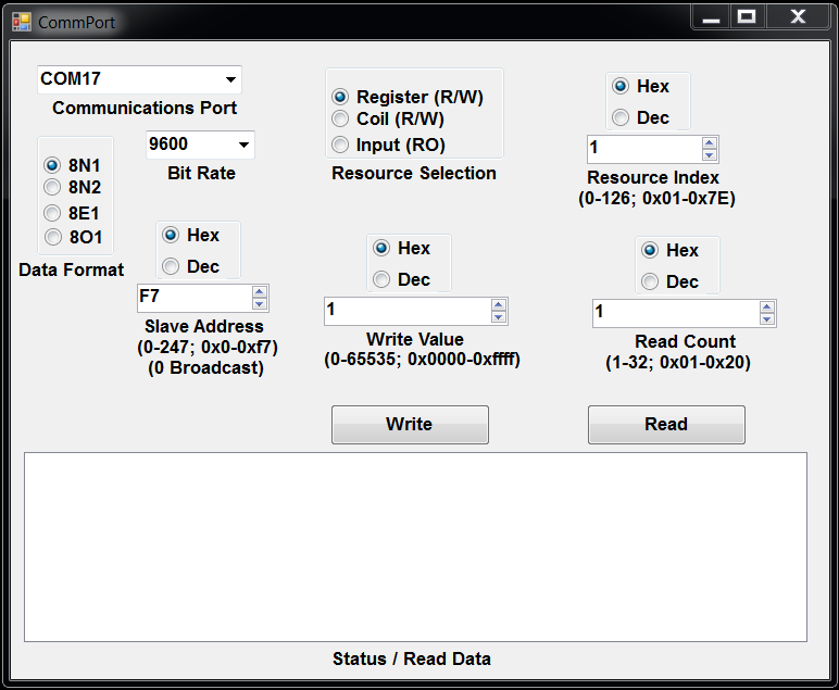
These programs are used to perform accesses to the Modbus devices register set. It allows the writing of arbitrary hex data to any hex register address one at a time and the reading of blocks of arbitrary data from any hex register addres displayed in hex, signed, or unsigned decimal. | These programs are used to perform accesses to the Modbus devices register set. It allows the writing of arbitrary hex data to any hex register address one at a time and the reading of blocks of arbitrary data from any hex register addres displayed in hex, signed, or unsigned decimal. | ||
Use of this utility requires the following steps: | |||
1. Select the COM port from the dro down box | |||
2. Select the bit rate from the drop down box | |||
3. Select the cirrect data format (8N1 is default) | |||
4. Enter the connected device slave address after selecting the format (Hex or Decimal) | |||
5. Select the resource type (Regoster, Input, or Coil) {{Notice|The coil functionality is currently not functional in Windows}} | |||
6a. Set the resoucw index (e.g., Register number) and count for reading | |||
6b. Set the resoucw index (e.g., Register number) and value for writing | |||
7. Click the appropriate button to read or write the device | |||
| Line 16: | Line 26: | ||
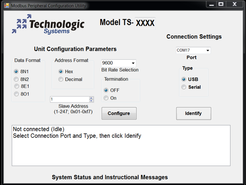
This program is used to perform configuration of a Modbus device. On older modbuc devices these settings (Slave address, Communications bit rate and data format, termination) would have been performed via DIP switches. This configuration information is stored in non-volatile memory on the device. | This program is used to perform configuration of a Modbus device. On older modbuc devices these settings (Slave address, Communications bit rate and data format, termination) would have been performed via DIP switches. This configuration information is stored in non-volatile memory on the device. | ||
Revision as of 14:02, 18 December 2014
Modbus Windows register access program: ModbusDeviceAccess
These programs are used to perform accesses to the Modbus devices register set. It allows the writing of arbitrary hex data to any hex register address one at a time and the reading of blocks of arbitrary data from any hex register addres displayed in hex, signed, or unsigned decimal.
Use of this utility requires the following steps: 1. Select the COM port from the dro down box 2. Select the bit rate from the drop down box 3. Select the cirrect data format (8N1 is default) 4. Enter the connected device slave address after selecting the format (Hex or Decimal) 5. Select the resource type (Regoster, Input, or Coil) Template:Notice 6a. Set the resoucw index (e.g., Register number) and count for reading 6b. Set the resoucw index (e.g., Register number) and value for writing 7. Click the appropriate button to read or write the device
Modbus Windows device configuration program: ModbusDeviceConfigure
This program is used to perform configuration of a Modbus device. On older modbuc devices these settings (Slave address, Communications bit rate and data format, termination) would have been performed via DIP switches. This configuration information is stored in non-volatile memory on the device.

