TS-4300: Difference between revisions
(Created page with "{{Infobox |title = TS-4300 |image = 200px |titlestyle = |headerstyle = background:#ccf; |labelstyle = width:33% |datastyle = |data...") |
No edit summary |
||
| Line 43: | Line 43: | ||
|data37 = Weight 20.4 (approx) | |data37 = Weight 20.4 (approx) | ||
}} | }} | ||
= Overview = | |||
The TS-4300 is a [http://www.embeddedarm.com/products/ts-socket.php TS-Socket] macrocontroller board based on the Cavium CNS3410 ARM11 System on Chip CPU running at 600MHz. The TS-4300 features 10/100 Ethernet, high speed USB host and device (OTG), and dual microSD card slots. | |||
= Getting Started = | |||
{{:Getting started}} | |||
== Development Kit and Accessories == | |||
The KIT-4500 includes the items that are commonly necessary for development with the TS-4500. | |||
{|class=wikitable | |||
|+ KIT-4500 Contents | |||
| Item | |||
| Description | |||
|- | |||
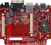
| [[File:TS-8200.jpg|200px|TS-8200]] | |||
| {{:TS-8200 description}} | |||
|- | |||
| [[File:Ts-enc820.jpg|200px|TS-ENC820]] | |||
| {{:TS-ENC820 description}} | |||
|- | |||
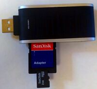
| [[File:SDKIT.jpeg|200px|MSD-2GB-USB-7500]] | |||
| {{:SDKIT description}} | |||
|- | |||
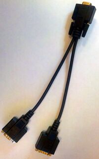
| [[File:CB-DB9Y.jpg|200px|CB-DB9Y]] | |||
| {{:CB-DB9Y description}} | |||
|- | |||
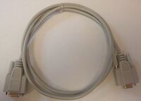
| [[File:CB7-05.jpg|200px|CB7-05]] | |||
| {{:CB7-05 description}} | |||
|- | |||
| [[File:CB-USB-AMBM.jpg|200px|CB-USB-AMBM]] | |||
| {{:CB-USB-AMBM description}} | |||
|- | |||
| [[File:CB-USB-AF5P.jpg|200px|CB-USB-AF5P]] | |||
| {{:CB-USB-AF5P description}} | |||
|- | |||
| [[File:PS-5VDC-REG-1AMP-BC.jpg|200px|PS-5VDC-REG-1AMP-BC]] | |||
| {{:PS-5VDC-REG-1AMP-BC description}} | |||
|} | |||
The other options include: | |||
{| class=wikitable | |||
|- | |||
! Item | |||
! Description | |||
|- | |||
| [[File:CN-TSSOCKET-M.jpg|200px|CN-TSSOCKET-M]] | |||
| {{:CN-TSSOCKET-M description}} | |||
|- | |||
| [[File:Wifi-n-usb.jpg|200px|WIFI-N-USB]] | |||
| {{:WIFI-N-USB description}} | |||
|} | |||
== Get a Console == | |||
The TS-4300 console (ttyS0) is a TTL UART at 115200 baud, 8n1 (8 data bits 1 stop bit), and no flow control. On the macrocontroller this is [[#TS-Socket Connector|CN2_93 (TX), CN2_95 (RX)]]. Various baseboards bring this out using different methods. The TS-8500 and TS-8200 baseboards bring out a DB9 connector with the console as RS232. Other baseboards have a jumper to switch between the console port and another serial port. Some baseboards require an adapter board like the TS-9449. Refer to the baseboard model you are using [Main_Page#Baseboards|here]] for more information on any specific jumpers or ports to connect to for console. | |||
{{Note|If DIO_9 is held low during boot until the red LED comes on (around 5 seconds), console will be redirected to XUART 0. On most baseboards where this is applicable, DIO_9 is an exposed button.}} | |||
{{:Console From Linux Workstation}} | |||
{{:Console from Windows Workstation}} | |||
== Booting up the board == | |||
{{Warning|Be sure to take appropriate Electrostatic Discharge (ESD) precautions. Disconnect the power source before moving, cabling, or performing any set up procedures. Inappropriate handling may cause damage to the board.}} | |||
If you are using one of our off the shelf baseboards you will need to refer to that baseboard's manual [Main_Page#Baseboards|here]]. Different baseboards use different power connectors, voltage ranges, and may have different power requirements. | |||
The TS-4500 macrocontroller only requires a 5V rail from the baseboard which may be regulated from other voltage ranges. Refer to the [[#TS-Socket Connector]] section for the POWER pins. While operating the board will typically idle at around 400mA@5V, but this can very slightly based on your application. For example, every USB device can consume up to 500mA@5V. The ethernet interface can draw around 50mA while the interface is up. Every DIO pin can source up to 12mA from the FPGA. A Sandisk SD card can draw 65mA@3.3V during a write. A typical power supply for just the TS-4500 will allow around 1A, but a larger power supply may be needed depending on your peripherals. | |||
Once you have applied power to your baseboard you should look for console output. The first output is from the bootrom: | |||
<pre style="font-family:monospace,Courier New ;background:black; width:18cm; white-space: pre-wrap; white-space: -moz-pre-wrap; word-wrap: break-word; color:white; "> | |||
>> TS-BOOTROM - built Sep 13 2012 13:45:30 | |||
>> Copyright (c) 2012, Technologic Systems | |||
>> ARM MPCore | |||
>> CPU: 600MHz, RAM: 400MHz | |||
>> RAM: 256MB | |||
>> Model: 0x4300 | |||
>> Booting from Flash | |||
. | |||
. | |||
. | |||
</pre> | |||
The "Booting From" message will indicate your boot media. The 3 dots after indicate steps of the booting procedure. The first dot means the MBR was copied into memory and executed. The next two dots indicate that the MBR executed and the kernel and initrd were found and copied to memory. | |||
The MODE1 and MODE2 signals both have pull-ups. For a logic 0 these should be pulled to ground with a 1k ohm resistor. | |||
{| class=wikitable | |||
|+ Boot Modes | |||
! Booot Device | |||
! MODE1 | |||
! MODE2 | |||
|- | |||
| XNAND | |||
| 1 | |||
| 1 | |||
|- | |||
| SD Card | |||
| 1 | |||
| 0 | |||
|- | |||
| Onboard Flash | |||
| 0 | |||
| 1 | |||
|- | |||
| Offboard Flash | |||
| 0 | |||
| 0 | |||
|} | |||
The offboard flash is only available on certain baseboards. | |||
Revision as of 17:23, 21 September 2012
 | |||
| Product Page | |||
| Documentation | |||
|---|---|---|---|
| Schematic | |||
| Mechanical Drawing | |||
| FTP Path | |||
| Processor | |||
| Cavium CNS3410 | |||
| 600MHz ARM11 | |||
| CPU Datasheet | |||
| RAM | |||
| 256MB or 512MB | |||
| FPGA | |||
| Xilinx Spartan-6 15K LUT6 FPGA | |||
| Reprogrammable with Opencore | |||
| DIO | |||
| 108 | |||
| External Interfaces | |||
| USB 2.0 2 hosts, 1 OTG | |||
| 1x 10/100 Ethernet | |||
| 1x I2C/TWI | |||
| SPI | |||
| 8x TTL UART, up to 8 without CAN | |||
| CAN | |||
| MUXBUS | |||
| Internal Storage Media | |||
| 2x SD | |||
| Power Requirements | |||
| 5VDC | |||
| Operates around 3W | |||
| Operating Temperature | |||
| |||
| |||
| Mechanical | |||
| 75.00mm X 55.00mm | |||
| Height 9.75mm (approx without baseboard) | |||
| Weight 20.4 (approx) | |||
Overview
The TS-4300 is a TS-Socket macrocontroller board based on the Cavium CNS3410 ARM11 System on Chip CPU running at 600MHz. The TS-4300 features 10/100 Ethernet, high speed USB host and device (OTG), and dual microSD card slots.
Getting Started
A Linux PC is recommended for development, and will be assumed for this documentation. For users in Windows or OSX we recommend virtualizing a Linux PC. Most of our platforms run Debian and if there is no personal distribution preference this is what we recommend for ease of use.
Virtualization
Suggested Linux Distributions
It may be possible to develop using a Windows or OSX system, but this is not supported. Development will include accessing drives formatted for Linux and often Linux based tools.
Development Kit and Accessories
The KIT-4500 includes the items that are commonly necessary for development with the TS-4500.
The other options include:
| Item | Description |
|---|---|
| The CN-TSSOCKET-M is the male connector which can be used for custom baseboard development. 2 Connectors are needed for each custom baseboard. | |

|
The WIFI-N-USB is an ASUS 802.11N adapter. See the WIFI-N-USB page for more details. |
Get a Console
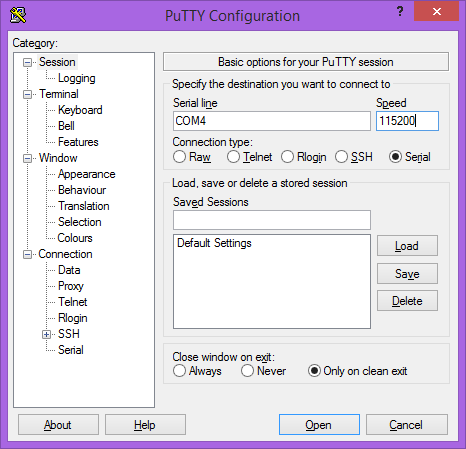
The TS-4300 console (ttyS0) is a TTL UART at 115200 baud, 8n1 (8 data bits 1 stop bit), and no flow control. On the macrocontroller this is CN2_93 (TX), CN2_95 (RX). Various baseboards bring this out using different methods. The TS-8500 and TS-8200 baseboards bring out a DB9 connector with the console as RS232. Other baseboards have a jumper to switch between the console port and another serial port. Some baseboards require an adapter board like the TS-9449. Refer to the baseboard model you are using [Main_Page#Baseboards|here]] for more information on any specific jumpers or ports to connect to for console.
| Note: | If DIO_9 is held low during boot until the red LED comes on (around 5 seconds), console will be redirected to XUART 0. On most baseboards where this is applicable, DIO_9 is an exposed button. |
Console from Linux
There are many serial terminal applications for Linux, three common used applications are picocom, screen, and minicom. These examples demonstrate all three applications and assume that the serial device is "/dev/ttyUSB0" which is common for USB adapters. Be sure to replace the serial device string with that of the device on your workstation.
picocom is a very small and simple client.
sudo picocom -b 115200 /dev/ttyUSB0
screen is a terminal multiplexer which happens to have serial support.
sudo screen /dev/ttyUSB0 115200
Or a very commonly used client is minicom which is quite powerful but requires some setup:
sudo minicom -s
- Navigate to 'serial port setup'
- Type "a" and change location of serial device to "/dev/ttyUSB0" then hit "enter"
- If needed, modify the settings to match this and hit "esc" when done:
     E - Bps/Par/Bits          : 115200 8N1
     F - Hardware Flow Control : No
     G - Software Flow Control : No
- Navigate to 'Save setup as dfl', hit "enter", and then "esc"
Console from Windows
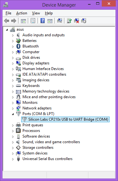
Putty is a small simple client available for download here. Open up Device Manager to determine your console port. See the putty configuration image for more details.
Booting up the board
| WARNING: | Be sure to take appropriate Electrostatic Discharge (ESD) precautions. Disconnect the power source before moving, cabling, or performing any set up procedures. Inappropriate handling may cause damage to the board. |
If you are using one of our off the shelf baseboards you will need to refer to that baseboard's manual [Main_Page#Baseboards|here]]. Different baseboards use different power connectors, voltage ranges, and may have different power requirements.
The TS-4500 macrocontroller only requires a 5V rail from the baseboard which may be regulated from other voltage ranges. Refer to the #TS-Socket Connector section for the POWER pins. While operating the board will typically idle at around 400mA@5V, but this can very slightly based on your application. For example, every USB device can consume up to 500mA@5V. The ethernet interface can draw around 50mA while the interface is up. Every DIO pin can source up to 12mA from the FPGA. A Sandisk SD card can draw 65mA@3.3V during a write. A typical power supply for just the TS-4500 will allow around 1A, but a larger power supply may be needed depending on your peripherals.
Once you have applied power to your baseboard you should look for console output. The first output is from the bootrom:
>> TS-BOOTROM - built Sep 13 2012 13:45:30
>> Copyright (c) 2012, Technologic Systems
>> ARM MPCore
>> CPU: 600MHz, RAM: 400MHz
>> RAM: 256MB
>> Model: 0x4300
>> Booting from Flash
.
.
.
The "Booting From" message will indicate your boot media. The 3 dots after indicate steps of the booting procedure. The first dot means the MBR was copied into memory and executed. The next two dots indicate that the MBR executed and the kernel and initrd were found and copied to memory.
The MODE1 and MODE2 signals both have pull-ups. For a logic 0 these should be pulled to ground with a 1k ohm resistor.
| Booot Device | MODE1 | MODE2 |
|---|---|---|
| XNAND | 1 | 1 |
| SD Card | 1 | 0 |
| Onboard Flash | 0 | 1 |
| Offboard Flash | 0 | 0 |
The offboard flash is only available on certain baseboards.
