TS-7250-V3 XBEE Header: Difference between revisions
From embeddedTS Manuals
Tag: Undo |
No edit summary |
||
| Line 52: | Line 52: | ||
|- | |- | ||
! Pin | ! Pin | ||
! IO Type | |||
! Signal | ! Signal | ||
|- | |- | ||
| 1 | | 1 | ||
| | |||
| VCC (XBEE_3.3V or NIMBEL_4.7V) | | VCC (XBEE_3.3V or NIMBEL_4.7V) | ||
|- | |- | ||
| 2 | | 2 | ||
| [[#IO specifications|CPU 3.3]] | |||
| [[#UARTs|ttymxc3 TXD]] | | [[#UARTs|ttymxc3 TXD]] | ||
|- | |- | ||
| 3 | | 3 | ||
| [[#IO specifications|CPU 3.3]] | |||
| [[#UARTs|ttymxc3 RXD]] | | [[#UARTs|ttymxc3 RXD]] | ||
|- | |- | ||
| 4 | | 4 | ||
| | |||
| GND | | GND | ||
|- | |- | ||
| 5 | | 5 | ||
| | | Open Drain <ref name=opendrainxbee /> | ||
| [[#GPIO|GPIO Bank 0 IO 10]] | |||
|- | |- | ||
| 6 | | 6 | ||
| | |||
| NIMBEL_4.7V | | NIMBEL_4.7V | ||
|- | |- | ||
| 7 | | 7 | ||
| | |||
| [[#USB|USB_XBEE_P]] | | [[#USB|USB_XBEE_P]] | ||
|- | |- | ||
| 8 | | 8 | ||
| | |||
| [[#USB|USB_XBEE_N]] | | [[#USB|USB_XBEE_N]] | ||
|- | |- | ||
| 9 | | 9 | ||
| | |||
| GND | | GND | ||
|- | |- | ||
| 10 | | 10 | ||
| | |||
| GND | | GND | ||
|- | |- | ||
| 11 | | 11 | ||
| | |||
| GND | | GND | ||
|- | |- | ||
| 12 | | 12 | ||
| [[#IO specifications|CPU 3.3]] | |||
| [[#UARTs|ttymxc3 CTS#]] | | [[#UARTs|ttymxc3 CTS#]] | ||
|- | |- | ||
| 13 | | 13 | ||
| | | Open drain <ref name=opendrainxbee>Driving high drives this pin to ground. Low tristates</ref> | ||
| [[#GPIO|GPIO Bank 2 IO 2]] | |||
|- | |- | ||
| 14 | | 14 | ||
| | |||
| 3.3V VREF | | 3.3V VREF | ||
|- | |- | ||
| 15 | | 15 | ||
| | |||
| GND | | GND | ||
|- | |- | ||
| 16 | | 16 | ||
| | |||
| GND | | GND | ||
|- | |- | ||
| 17 | | 17 | ||
| | |||
| NC | | NC | ||
|- | |- | ||
| 18 | | 18 | ||
| | |||
| NC | | NC | ||
|- | |- | ||
| 19 | | 19 | ||
| | |||
| NC | | NC | ||
|- | |- | ||
| 20 | | 20 | ||
| Open Drain <ref name=opendrainxbee /> | |||
| [[#GPIO|GPIO Bank 0 IO 31]] <ref>This pin is inverted, Setting to 1 drives pin 2 low.</ref> | | [[#GPIO|GPIO Bank 0 IO 31]] <ref>This pin is inverted, Setting to 1 drives pin 2 low.</ref> | ||
|} | |} | ||
Revision as of 16:16, 22 September 2023
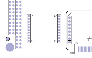
The CN20 header is a 2mm pitch 2x10 header which supports XBEE form factor modules. These include Nimbelink and Digi cell modems, Zigbee, Digi mesh, and other third party radios.
For Cell radios that use USB this must be enabled. This turns off USB to the bottom port on the dual high type A connector. Only enable if this is compatible with your module:
# Turn on the USB
gpioset 0 11=1
This header can provide 3.3V or 4V as some cell radios require higher voltage. Only enable one power supply to match your radio:
## For 3.3V modules:
#gpioset 6 4=1

## For 4V modules:
#gpioset 6 11=1
For serial modules refer to these related links:
- Technologic Systems: A friendly introduction to XBEE
- Digi's C library for XBEE API mode
- Digi's Python XBEE library
- Digi's C# Library
- Digi's Java Library
- libxbee3 (community XBEE library)
This sample code can be used to verify connectivity to the serial based modules:
wget http://ftp.embeddedTS.com/ftp/ts-arm-sbc/ts-7840-linux/samples/xbeetest.c
gcc xbeetest.c -o xbeetest

gpioset 6 4=1 # Turn on only 3.3V

./xbeetest /dev/ttymxc3
This will print out the module information such as:
XBee3 Zigbee TH RELE: 100A
Build: Apr 16 2020 19:00:33
HV: 424E
Bootloader: 181 Compiler: 8030001
Stack: 6710
OK
| Signals | Pin Layout | |||||||||||||||||||||||||||||||||||||||||||||||||||||||||||||||
|---|---|---|---|---|---|---|---|---|---|---|---|---|---|---|---|---|---|---|---|---|---|---|---|---|---|---|---|---|---|---|---|---|---|---|---|---|---|---|---|---|---|---|---|---|---|---|---|---|---|---|---|---|---|---|---|---|---|---|---|---|---|---|---|---|
|
