NOTICE: This article is a work in progress. If you have questions about using the TS-8820-4720, please call our support team, or email support@embeddedarm.com. Thanks!
Overview
The TS-8820-4720 is an industrial Building Controller that knows how to Linux.
Getting Started
The Getting Started section will go here.
Features
Enumerated list of device functions here.
External Interfaces
Terminal Blocks
| Note:
|
If you have a REV A board disregard the P1-P10 labeling as printed on the PCB.
|
|
|
|
|
|
|
|
|
|
|
P9
| Pin
|
Description
|
| 1
|
DAC 3
|
| 2
|
Ground
|
| 3
|
DAC 4
|
| 4
|
Ground
|
| 5
|
Spare 1
|
| 6
|
Spare 2
|
| 7
|
Spare 3
|
| 8
|
Spare 4
|
| 9
|
Spare 5
|
| 10
|
Spare 6
|
| 11
|
Spare 7
|
| 12
|
Spare 8
|
|
P10
| Pin
|
Description
|
| 1
|
Not Connected
|
| 2
|
Not Connected
|
| 3
|
ISO Common
|
| 4
|
ISO Common
|
| 5
|
XUART0 ISO RS485+
|
| 6
|
XUART0 ISO RS485-
|
| 7
|
XUART1 ISO RS232 TXD
|
| 8
|
XUART1 ISO RS232 RXD
|
| 9
|
Not Connected
|
| 10
|
CAN Common
|
| 11
|
CAN_H
|
| 12
|
CAN_L
|
|
Ethernet Connector
The TS-8820 can connect to any Ethernet LAN. Ethernet is fully supported by any TS-SOCKET macrocontroller. The Ethernet connector includes LEDs indicating link and activity. The link LED should be on whenever the TS-8820 is powered and connected to a LAN. This connector allows the TS-8820 to be powered by PoE.
USB Host
The USB is available on two ports as a USB 2.0 host.
|
|
| Header PIN
|
Name
|
| 1
|
USB_5V
|
| 2
|
HOSTA_USB_M
|
| 3
|
HOSTA_USB_P
|
| 4
|
GND
|
|
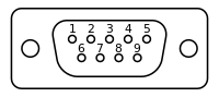
DB9 Connector
|
| Pin
|
Description
|
| 1
|
XUART4 RS485+
|
| 2
|
Debug Console RS232 RXD
|
| 3
|
Debug Console RS232 TXD
|
| 4
|
Not Connected
|
| 5
|
Ground
|
| 6
|
XUART4 RS485-
|
| 7
|
XUART2 RS232 TXD
|
| 8
|
XUART2 RS232 RXD
|
| 9
|
Not Connected
|
|
TS-8820 Register Map
This register map assumes a base address offset. The offset when using the TS-4720 is 0x80008000. This address must first be activated using the MUXBUS enable and timing registers on the CPU module. On the TS-4720, write 0xF3FF to the address 0x80004004. Sample code for accessing the functions described in this table are largely encompassed by the ts8820ctl software available on the TS FTP Site.
| Offset
|
Bits
|
Description
|
| 0x0
|
15:0
|
Model ID: Reads 0x8820
|
| 0x2
|
15:11
|
Reserved
|
| 10
|
Pull-up 5-8 enable
|
| 9
|
Pull-up 3-4 enable
|
| 8
|
Pull-up 1-2 enable
|
| 7
|
H-bridge 2 enable (contacts go high-Z otherwise)
|
| 6
|
H-bridge 1 enable (contacts go high-Z otherwise)
|
| 5
|
H-bridge 2 direction
|
| 4
|
H-bridge 1 direction
|
| 3:0
|
FPGA Revision
|
| 0x4
|
15:14
|
Reserved
|
| 13:0
|
Digital inputs 14:1
|
| 0x6
|
15:10
|
Reserved
|
| 9:0
|
SRAM Page register
|
| 0x8
|
15:12
|
Reserved
|
| 11:6
|
Override Digital Outputs 6:1 with PWM
|
| 5:0
|
Digital Output Values 6:1
|
| 0xa
|
15:0
|
Reserved
|
| 0xc
|
15:0
|
Reserved
|
| 0xe
|
15:0
|
Reserved
|
| 0x10
|
15:13
|
PWM #1 Prescaler
|
| 12:0
|
PWM #1 Duty Cycle
|
| 0x12
|
15:13
|
PWM #2 Prescalar
|
| 12:0
|
PWM #2 Duty Cycle
|
| 0x14
|
15:13
|
PWM #3 Prescaler
|
| 12:0
|
PWM #3 Duty Cycle
|
| 0x16
|
15:13
|
PWM #4 Prescaler
|
| 12:0
|
PWM #4 Duty Cycle
|
| 0x18
|
15:13
|
PWM #5 Prescaler
|
| 12:0
|
PWM #5 Duty Cycle
|
| 0x1a
|
15:13
|
PWM #6 Prescaler
|
| 12:0
|
PWM #6 Duty Cycle
|
| 0x1c
|
15:13
|
PWM #7 Prescaler
|
| 12:0
|
PWM #7 Duty Cycle
|
| 0x1e
|
15:13
|
PWM #8 Prescaler
|
| 12:0
|
PWM #8 Duty Cycle
|
| 0x20
|
15:0
|
Pulse Counter #1 (RO)
|
| 0x22
|
15:0
|
Pulse Counter #2 (RO)
|
| 0x24
|
15:0
|
Pulse Counter #3 (RO)
|
| 0x26
|
15:0
|
Pulse Counter #4 (RO)
|
| 0x28
|
15:0
|
Pulse Counter #5 (RO)
|
| 0x2a
|
15:0
|
Pulse Counter #6 (RO)
|
| 0x2c
|
15:0
|
Pulse Counter #7 (RO)
|
| 0x2e
|
15:0
|
Pulse Counter #8 (RO)
|
| 0x30
|
15:0
|
Pulse Counter #9 (RO)
|
| 0x32
|
15:0
|
Pulse Counter #10 (RO)
|
| 0x34
|
15:0
|
Pulse Counter #11 (RO)
|
| 0x36
|
15:0
|
Pulse Counter #12 (RO)
|
| 0x38
|
15:0
|
Pulse Counter #13 (RO)
|
| 0x3a
|
15:0
|
Pulse Counter #14 (RO)
|
| 0x3c
|
15:0
|
Reserved
|
| 0x3e
|
15:0
|
Reserved
|
| 0x80
|
15:0
|
ADC Core ID (reads 0xadc1)
|
| 0x82
|
15:8
|
ADC Channel Mask (0 = do not save channel data)
|
| 7:6
|
Highest number chip to use (0-3, if 01 then sample chip 0 and chip 1)
|
| 5
|
1 = Force standby
|
| 4
|
1 = Use standby between samples to save power
|
| 3
|
1 = Smart DMA IRQ mode
|
| 2
|
1 = Enable IRQ
|
| 1
|
1 = Collect samples, 0 = stop
|
| 0
|
1 = Reset ADC chips and all FIFOs
|
| 0x84
|
15
|
1 = There has been a FIFO overflow since last reset
|
| 14:0
|
Number of samples available to be read
|
| 0x86
|
15:0
|
Sample Data (RO)
|
| 0x88
|
15:0
|
Sampling period LSB (RW)
|
| 0x8a
|
15:0
|
Sampling period MSB (RW)
|
| 0x8c
|
15:0
|
IRQ Threshold (RW)
|
| 0x8e
|
15:0
|
DMA transfer size for smart mode (RW) (TODO)
|
| 0x90
|
15:0
|
Reserved
|
| 0x92
|
15:0
|
Reserved
|
| 0x94
|
15:0
|
Reserved
|
| 0x96
|
15:0
|
Reserved
|
| 0x98
|
15:0
|
Reserved
|
| 0x9a
|
15:0
|
Reserved
|
| 0x9c
|
15:0
|
Reserved
|
| 0x9e
|
15:0
|
Reserved
|
| 0xa0
|
15:0
|
DAC 1 Control Register
|
| 0xa2
|
15:0
|
DAC 2 Control Register
|
| 0xa4
|
15:0
|
DAC 3 Control Register
|
| 0xa6
|
15:0
|
DAC 4 Control Register
|
Product Notes
Some parts may cause cancer in the State of California.

