TS-IRIDIUM: Difference between revisions
(fixed link to schematic.) |
|||
| Line 8: | Line 8: | ||
|data1 = [http://www.embeddedarm.com/products/board-detail.php?product=TS-IRIDIUM Product Page] | |data1 = [http://www.embeddedarm.com/products/board-detail.php?product=TS-IRIDIUM Product Page] | ||
|header2 = Documents | |header2 = Documents | ||
|data3 = [ | |data3 = [https://www.embeddedarm.com/documentation/ts-iridium-schematic.pdf Schematic] | ||
|data4 = [http://www.celestech.com/Partners/IridiumSBDProducts.html Celestech] | |data4 = [http://www.celestech.com/Partners/IridiumSBDProducts.html Celestech] | ||
}} | }} | ||
Revision as of 14:38, 15 August 2019
 | |
| Product Page | |
| Documents | |
|---|---|
| Schematic | |
| Celestech |
Overview
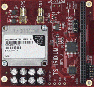
The TS-Iridium provides a UART connection over PC104.
Full Iridium Documentation
To receive the full documentation for this board you must contact your satellite service provider. This documentation is only intended to get the UART connection established.
Configuration
You must alter IRQ and the IO address to reflect your pin configuration.
TS-72XX
This series will automatically detect the COM port and create it with /dev/tts/<COM number>. The COM number will depend on your pin configuration.
TS-7800
This example is from Debian:
. /initrd/ts7800.subr
pc104on
modprobe ts7800_isa16550 irq=7 io=0x3F8
To view if it loaded correctly, run 'dmesg' and you should find a line similar to this:
serial8250: ttyS2 at MMIO 0xee0003f8 (irq = 71) is a 16550A
So in this case the COM device will be /dev/ttyS2.
Testing the Iridium
To test communication, you can use picocom or any similar serial control application. Connect at 19200 8n1 with no flowcontrol and send an "AT". The modem should echo back "OK". Replace the tty device with the corrected location for your device.
root@ts7800:# picocom /dev/ttyS2 -b 19200
picocom v1.4

port is        : /dev/ttyS2
flowcontrol    : none
baudrate is    : 19200
parity is      : none
databits are   : 8
escape is      : C-a
noinit is      : no
noreset is     : no
nolock is      : no
send_cmd is    : ascii_xfr -s -v -l10
receive_cmd is : rz -vv

Terminal ready
AT
OK
COM/IO Selection
| COM | Address | JP1 | JP2 | JP3 |
|---|---|---|---|---|
| COM1 | 3F8 | Off | Off | Off |
| COM2 | 2F8 | On | Off | Off |
| COM3 | 3E8 | Off | On | Off |
| COM4 | 2E8 | Off | On | On |
| COM5 | 3A8 | Off | Off | On |
| COM6 | 2A8 | On | Off | On |
| COM7 | 3A0 | Off | On | On |
| COM8 | 2A0 | On | On | On |
PLD Base Address
| JP4 Off | JP4 On |
|---|---|
| 140 to 14F | 190 to 19F |
PLD Registers
Base + 0 will always return 0x9. This can be used to detect the presence of the board.
Base + 1 will return 0x6 on the first access, 0x7 on the second, 0x8 on the third, and on the 4th access it will return the PLD version.
Base + 2:
| Bit | Access | Function |
|---|---|---|
| 0 | R | JP1 On |
| 1 | R | JP2 On |
| 2 | R | JP3 On |
| 3 | R | JP4 On |
Base + 3:
| Bit | Access | Function |
|---|---|---|
| 0 | RW | Modem Power Toggle |
| 1 | R | Modem Power Status |
| 2 | R | LED Status (1 on) |
| 3 | R | JP5 On |
Iridium Power
With JP5 enabled, the Iridium modem will receive power by default. With either configuration of that jumper you can always toggle the power from the PLD. The modem typically takes 750ms to power on, and can take up to 3s to turn off.