TS-4600
 | |
| Product Page | |
| Product Images | |
| Specifications | |
| Documentation | |
|---|---|
| Schematic | |
| Mechanical Drawing | |
| FTP Path | |
| Processor | |
| NXP i.MX286 | |
|
454 MHz Arm®v5TE Arm926EJ-S™ (Arm9™-compatible) | |
| i.MX286 Product Page | |
| CPU Reference Manual |
Overview
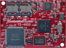
The TS-4600 was released June 2013. This is a small embedded board with an NXP i.MX283 454Mhz ARM9 CPU, Lattice XP2 5k FPGA, and 128-256MB DDR2.
Getting Started
A Linux workstation is recommended and assumed for development using this documentation. For users in Windows or OSX, we recommend virtualizing Linux. Most of our platforms run Debian, which is recommended for ease of use if there is no personal distribution preference.
Virtualization
Suggested Linux Distributions
Development using a Windows or OSX system may be possible but is not supported. Development will include accessing drives formatted for Linux and often Linux-based tools.
Development Kit and Accessories
The KIT-4600 includes the items that are commonly necessary for development with the TS-4600.
| Item | Description |

|
The TS-8200 is a baseboard that brings out RS232, RS485, CAN, Ethernet, USB, and provides a switching regulator that can accept 5-12V. |

|
This enclosure measures 139.88mm (5.507 in.) W x 102.02mm (4.016 in.) D x 35.06mm (1.380 in.) H. The end-plate brings out 1x 10/100 Ethernet port, 1x USB Host port, 1 USB Device port, 2 user controlled red and green LEDs, multipurpose reset/script button, power input and COM port. The power source is either 5-12V DC through a commercial-grade barrel connector on the front of the unit or USB cable via USB Device port. |

|
A Sandisk MicroSD card with a Vivitar SD reader. We recommend Sandisk SD cards as that is what we use for testing. Whenever we receive batches of SD cards from our suppliers, we will pull a few cards for testing to ensure they behave within our expectations. The Vivitar reader is also recommended because it was tested to work with the most SD cards, and it does not have a potentially damaging voltage drop that many consumer SD readers have. |

|
The CB-DB9Y is a splitter cable used to bring out multiple uarts on the same header. |

|
The CB7-05 is a 5 foot null modem cable. This is commonly used to connect to your workstation. |

|
This is a USB A male to USB B male which is commonly used to connect the board to your PC as a USB device. This is also used for connecting the TS-9449 to your workstation for a USB to serial console. |

|
The CB-USB-AF5P connects from a standard 5 pin 0.1" pitch header to a USB A host. This can be used to expose a single USB port while keeping the rest internal to your own enclosure. |

|
This is a 5V 1A DC power supply on a center pin positive barrel connector. Optionally type I or C adapters are available and will ship with the product if ordered to a country where this specific adapter is required. If you require one of these adapters it is recommended to put this in the comments for your order. |
The other options include:
| Item | Description |
|---|---|
| The CN-TSSOCKET-M is the male connector which can be used for custom baseboard development. 2 Connectors are needed for each custom baseboard. | |

|
The WIFI-N-USB is an ASUS 802.11N adapter. See the WIFI-N-USB page for more details. |
Booting up the board
| WARNING: | Be sure to take appropriate Electrostatic Discharge (ESD) precautions. Disconnect the power source before moving, cabling, or performing any set up procedures. Inappropriate handling may cause damage to the board. |
If you are using one of our off the shelf baseboards you will need to refer to that baseboard's manual here. Different baseboards use different power connectors, voltage ranges, and may have different power requirements.
The System-on-Module (SoM) only requires a 5V rail from the baseboard which may be regulated from other voltage ranges. Refer to the #TS-Socket Connector section for the POWER pins. While operating the board will typically idle at around 320mA@5V, but this can vary slightly based on your application. For example, every USB device can consume up to 500mA@5V. The ethernet interface can draw around 50mA while the interface is up. Every DIO pin can source up to 12mA from the FPGA. A Sandisk SD card can draw 65mA@3.3V during a write, and larger cards can consume more. A typical power supply for just the SoM will allow around 1A, but a larger power supply may be needed depending on your peripherals.
Once you have applied power to your baseboard you should look for console output. The next section of the manual provides information on getting the console connected. The first output is from the bootrom:
HTLLLLLLLLLLLLLLLLLLLLLLLLLLLLLLLLLLLLLLLLLLLLLLLLLLLLLLLLLLLLLLLLLLLLLLFLC
>> TS-BOOTROM - built Sep  4 2013 14:49:24
>> Copyright (c) 2013, Technologic Systems
LLCLLLLLLLFLCLLJUncompressing Linux... done, booting the kernel.
Booted in 3.89s
Initramfs Web Interface: http://ts4600-4f3029.local
#
The i.MX28 internal bootrom prints out the strings of letters to indicate various stages of its internal process. The TS-BOOTROM build date reflects when then imx-bootlets were built. When building a custom kernel from source this date will be changed and may not always reflect the kernel build date.
Get a Console
Option 1: Telnet
If your system is configured with zeroconf support (Avahi, Bonjour, etc) you can simply connect with:
telnet ts4600-<last 6 characters of the MAC address>.local
# You will need to use your TS-4600 MAC address, but
# for example if you mac is 00:d0:69:01:02:03
telnet ts4600-010203.local
When the board first powers up it has two network interfaces. The first interface eth0 is configured to use IPv4LL, and eth0:0 is configured to use DHCP. The board broadcasts using multicast DNS advertising the _telnet._tcp service. You can use this to query all of the available TS-4600s on the network.
From Linux you can use the avahi commands to query for all telnet devices with:
avahi-browse _telnet._tcp
Which would return:
+   eth0 IPv4 TS-4600 console [4f47a5]                      Telnet Remote Terminal local
+   eth0 IPv4 TS-4600 console [4f471a]                      Telnet Remote Terminal local
This will show you the mac address you can use to resolve the board. In this case you can connect to either ts4600-4f47a5.local or ts4600-4f471a.local
From Windows you can use Bonjour Print Services to get the dns-sd command. OSX also comes preinstalled with the same command. Once this is installed you can run:
dns-sd -B _telnet._tcp
Which will return:
Browsing for _telnet._tcp
Timestamp     A/R Flags if Domain                    Service Type              Instance Name
10:27:57.078  Add     3  2 local.                    _telnet._tcp.             TS-4600 console [4f47a5]
10:27:57.423  Add     3  2 local.                    _telnet._tcp.             TS-4600 console [4f471a]
This will show you the mac address you can use to resolve the board. In this case you can connect to either ts4600-4f47a5.local or ts4600-4f471a.local
Option 2: Serial Console
With the development kit you should have the TS-8200 which brings out the debug console ttyAM0 from the ARM processor as RS232. Custom baseboards should emulate the TS-8200 for bringing out console. See the schematics available on the TS-8200 page. The console from the UART will use 115200 baud, 8n1 (8 data bits 1 stop bit), and no flow control.
| Note: | If DIO_9 is held low during boot until the red LED comes on (around 5 seconds), console will be redirected to XUART 1. On most baseboards where this is applicable, DIO_9 is an exposed button. |
Console from Linux
There are many serial terminal applications for Linux, three common used applications are picocom, screen, and minicom. These examples demonstrate all three applications and assume that the serial device is "/dev/ttyUSB0" which is common for USB adapters. Be sure to replace the serial device string with that of the device on your workstation.
picocom is a very small and simple client.
sudo picocom -b 115200 /dev/ttyUSB0
screen is a terminal multiplexer which happens to have serial support.
sudo screen /dev/ttyUSB0 115200
Or a very commonly used client is minicom which is quite powerful but requires some setup:
sudo minicom -s
- Navigate to 'serial port setup'
- Type "a" and change location of serial device to "/dev/ttyUSB0" then hit "enter"
- If needed, modify the settings to match this and hit "esc" when done:
     E - Bps/Par/Bits          : 115200 8N1
     F - Hardware Flow Control : No
     G - Software Flow Control : No
- Navigate to 'Save setup as dfl', hit "enter", and then "esc"
Console from Windows
Putty is a small simple client available for download here. Open up Device Manager to determine your console port. See the putty configuration image for more details.


Initramfs
When the board first boots up, it will present output on the console similar to:
HTLLLLLLLLLLLLLLLLLLLLLLLLLLLLLLLLLLLLLLLLLLLLLLLLLLLLLLLLLLLLLLLLLLLLLLFLC
>> TS-BOOTROM - built Sep  4 2013 14:49:24
>> Copyright (c) 2013, Technologic Systems
LLCLLLLLLLFLCLLJUncompressing Linux... done, booting the kernel.
Booted in 3.89s
Initramfs Web Interface: http://ts7600-4f3029.local
#
| Note: | Printed version dates may be different depending on ship date and the image used. |
This is a minimalistic initial ram filesystem that includes our specific utilities for the board, and is then used to bootstrap the Linux root. The initramfs is built into the kernel image so it cannot be modified without rebuilding the kernel, but it does include 8-bits for common configuration option we call soft jumpers.
Most development needs can be satisfied by booting to the Debian filesystem which can be reached by typing "exit" through the serial or telnet console, or by setting the soft jumper JP1 to make the unit automatically boot to Debian:
tshwctl --setjp 1
| Jumper | Function |
| 1 | Boot automatically to Debian [1] |
| 2 | Reserved |
| 3 | Reserved |
| 4 | Reserved |
| 5 | Reserved |
| 6 | Reserved |
| 7 | Boot as fast as possible [2] |
| 8 | Reserved |
There are 2 ways to manipulate soft jumpers on the device. The web interface at "http://<model>-<last 6 chars of the MAC>.local" has a list of checkboxes that will immediately change the values. The tshwctl command can also be used from the commandline:
# Boot automatically to Debian:
tshwctl --setjp=1

# Or revert to the initramfs:
tshwctl --removejp=1
| Note: | The nov052013 image has a file in the linux root, /ts/fastboot. This file will override the JP1 settings and always boot to the initramfs. This file must be removed for JP1 to act as described above. This file will be removed from future images. |
If it is not possible to access the serial console, ensure Debian's network settings are configured first before booting directly to Debian. Once JP1 is enabled, the initramfs does not run ifplugd/udhcpc to configure the network.
We recommend most development be done in Debian, however many applications are capable of running from the initramfs. The initramfs itself cannot be easily modified, and it is not recommended to do so. The initramfs however has several hooks for applications to use. Debian is mounted at /mnt/root as a read only filesystem which includes the /ts/ directory that includes several hooks.
/mnt/root/ts/init
For headless applications it is possible to create a bash script in Debian at /ts/init with any initialization required. This does not use the same $PATH as Debian, so any applications called from this environment need to use the full path as they would be from the initramfs. The init file does not exist by default and must be created:
#!/bin/sh

/path/to/your/application &
USB update mechanism, tsinit
For implementing a custom production process or applying updates in the field, this SBC is capable of detecting a USB device and running a script. The behavior of this process can be tuned, see more information in the config section below.
There are a few requirements of this script: the USB device itself must be the first or only USB storage device connected, the script must be on the first partition of said USB device and be named tsinit and the script must be world executable. PATH is passed to the tsinit script, it is what the initramfs environment PATH is, if additional PATHs are required that can be added in the tsinit script. Standard in/out are the standard console port, this means either the serial debug port, or telnet. Please note that if using telnet, output may be missed as the scripts will not wait for a telnet connection to establish, it is recommended to use a real serial port because of this.
During the USB update process, the first partition of the USB drive is mounted to /mnt/usbdev/ of the initramfs. Then the update mechanism attempts to execute /mnt/usbdev/tsinit and thus launches the script. As stated above, PATH is passed to the script as well as standard in and out (linked to the console port) allowing for printed information in the script to appear on the terminal.
/mnt/root/ts/initramfs-xinit
Graphical applications should use /ts/initramfs-xinit. The xinit file is used to start up a window manager and any applications. The default initramfs-xinit starts a webbrowser viewing localhost:
#!/bin/sh
# Causes .Xauthority and other temp files to be written to /root/ rather than default /
export HOME=/root/
# Disables icewm toolbars
export ICEWM_PRIVCFG=/mnt/root/root/.icewm/

# minimalistic window manager
icewm-lite &

# this loop verifies the window manager has successfully started
while ! xprop -root | grep -q _NET_SUPPORTING_WM_CHECK
do
    sleep 0.1
done

# This launches the fullscreen browser.    If the xinit script ever closes, x11 will close.  This is why the last
# command is the target application which is started with "exec" so it will replace the xinit process id.
exec /usr/bin/fullscreen-webkit http://localhost
/mnt/root/ts/config
This config file can be used to alter many details of the initramfs boot procedure.
## This file is included by the early init system to set various bootup settings.
## if $jp7 is enabled none of these settings will be used.

## Used to control whether the FPGA is reloaded through software.
## 1 to enable reloading (default)
## 0 to disable reloading
#CFG_FPGARELOAD="0"

## By default dns-sd is started which advertises the ts<model>-<last 6 of mac>
## telnet and http services using zeroconf.
## 1 to enable dns-sd (default)
## 0 to disable dns-sd
#CFG_DNSSD_EN="0"

## This is used to discover hosts and advertise this host over multicast DNS.
## 1 to enable mdns (default)
## 0 to disable mdns
#CFG_MDNS_EN="0"

## ifplugd is started in the initramfs to start udhcpc, and receive an ipv4ll
## address.
## 1 to enable ifplugd (default)
## 0 to disable ifplugd
#CFG_IFPLUGD_EN="0"

## By default telnet is started on port 2323.
## 1 to enable telnet (default)
## 0 to disable telnet
##CFG_TELNET_EN="0"

## The busybox webserver is used to display a diagnostic web interface that can
## be used for development tasks such as rewriting the SD or uploading new
## software
## 1 to enable (default)
## 0 to disable
##CFG_HTTPD_EN="0"

## This eanbles a reset switch on DIO 29 (TS-7700), or DIO 9 on all of the
## boards.  Pull low to reset the board immediately.
## 1 to enable the reset sw (default)
## 0 to disable
#CFG_RESETSW_EN="0"

## The console is forwarded through xuartctl which makes the cpu console available
## over telnet or serial console.
## 1 to enable network console (default)
## 0 to disable network console
#CFG_NETCONS_EN="0"

## By default Alsa will put the SGTL5000 chip into standby after 5 seconds of
## inactivity.  This is desirable in that it results in lower power consumption,
## but it can result in an audible popping noise.  This setting prevents
## standby so the pop is never heard.
## 1 to disable standby
## 0 to enable standby (default)
#CFG_SGTLNOSTBY="1"

## xuartctl is used to access the FPGA uarts.  By default it is configured to
## be IRQ driven which is optimized for best latency, but at the cost of
## additional CPU time.  You can reduce this by specifying a polling rate.
## The xuartctl process also binds to all network interfaces which can provide a
## simple network API to access serial ports remotely.  You can restrict this to
## the local network with the bind option.
## Configure XUART polling 100hz
## Default is IRQ driven
CFG_XUARGS="--irq=100hz"
## Configure xuartctl to bind on localhost
## Default binds on all interfaces
#CFG_XUARGS="--bind 127.0.0.1 --irq=100hz"
## For a full list of arguments, see the xuartctl documentation here:
## http://docs.embeddedts.com/wiki/Xuartctl#Usage

## By default the system will probe for up to 10s on USB for a mass storage device
## and mount the first partition.  If there is an executable /tsinit script in the
## root this will be executed.  This is intended for production or updates.
## 2 to enable USB init always (adds 10s or $CFG_USBTIME to startup)
## 1 to enable USB init when jp1=0 (default)
## 0 to disable USB init always
#CFG_USBINIT="2"

## The USB init script by default blocks for 10s to detect a thumb drive that
## contains the tsinit script.  Most flash media based drives can be detected
## in 3s or less.  Some spinning media drives can take 10s, or potentially longer.
## This options is the number of seconds to wait before giving up on the
## mass storage device.
#CFG_USBTIME="3"

### TS-8700
## Using the TS-8700 baseboard the board will by default initialze all of the
## ethernet ports as individual vlan ports, eg eth0.1, eth0.2, eth0,3, and eth0.4
## The alterantive option sets Port A to eth0.1, and Ports B-D to eth0.2, or
## you can configure all ethernet ports as a single eth0 port.
## See http://docs.embeddedts.com/wiki/TS-8700 for more information
## 2 disables any vlan and passes through all interfaces to eth0
## 1 enables "WLAN" mode setting "A" as eth0.1, and all others as eth0.2
## 0 enables "VLAN" mode for 4 individual ports (default)
#CFG_4ETH="1"

### TS-4712 / TS-4720
## These boards include an onboard switch with 2 external ports.  By default
## the switch will detect if it is on a known baseboard that supports the second
## ethernet switch port, and set up VLAN rules to define eth0.1 and eth0.2.  The
## other option is to configure the switch to pass through the packets to eth0
## regarless of port.
## 2 Disable VLAN and pass through to eth0
## 1 Enable VLAN on all baseboards
## 0 Enable VLAN on supported baseboards (Default)
#CFG_2ETH="1"
Debian Configuration
For development, it is recommended to work directly in Debian on the SD card. Debian provides many more packages and a much more familiar environment for users already versed in Debian. Through Debian it is possible to configure the network, use the 'apt-get' suite to manage packages, and perform other configuration tasks. Out of the box the Debian distribution does not have any default username/password set. The account "root" is set up with no password configured. It is possible to log in via the serial console without a password but many services such as ssh will require a password set or will not allow root login at all. It is advised to set a root password and create a user account when the unit is first booted.
| Note: | Setting up a password for root is only feasible on the uSD image. |
It is also possible to cross compile applications. Using a Debian host system will allow for installing a cross compiler to build applications. The advantage of using a Debian host system comes from compiling against libraries. Debian cross platform support allows one to install the necessary development libraries on the host, building the application on the host, and simply installing the runtime libraries on the target device. The library versions will be the same and completely compatible with each other. See the respective Debian cross compiling section for more information.
Configuring the Network
This board includes a Marvell switch chip which allows 2 separate networks using the same network interface. See the Ethernet port section for more information on the switch settings. When the switch is configured for 2 separate networks (as it is by default), the eth0 interface should not be directly configured. The switch will provide the eth0.1 and eth0.2 interfaces which can be configured. If the switch is configured to pass through, then the eth0 interface should be used as normal.
The board is initially configured to boot to the initramfs. While in this state ifplugd will automatically assign an IP address, and even if you type "exit" to boot to Debian it will retain the address it was assigned. If you need to boot to the full Debian, networking should first be set up in the /etc/network/interfaces file. As an example, to get dhcp from eth0.1: Open /etc/network/interfaces
# We always want the loopback interface.
auto lo
iface lo inet loopback

auto eth0.1
iface eth0.1 inet dhcp
Once this file is set up, either reboot or "/etc/init.d/networking restart" for this to take effect.
From almost any Linux system you can use "ip" or the ifconfig/route commands to manually set up the network. To configure the network interface manually you can use the same set of commands in the initramfs or Debian.
# NOTE:  These are generic examples.  Be sure to read the entire networking section before trying any of these.
# Bring up the CPU network interface (for systems with only one Ethernet)
ifconfig eth0 up

# Or if you're on a baseboard with a second ethernet port, you can use that as:
ifconfig eth1 up

# Or if you're on a TS-7250-V2...
ifconfig eth0.1 up
ifconfig eth0.2 up

# Set an ip address (assumes 255.255.255.0 subnet mask)
ifconfig eth0 192.168.0.50

# Set a specific subnet
ifconfig eth0 192.168.0.50 netmask 255.255.0.0

# Configure your route.  This is the server that provides your internet connection.
route add default gw 192.168.0.1

# Edit /etc/resolv.conf for your DNS server
echo "nameserver 192.168.0.1" > /etc/resolv.conf
Most commonly networks will offer DHCP which can be set up with one command:
Configure DHCP in Debian:
# To setup the default CPU ethernet port
dhclient eth0
# Or if you're on a baseboard with a second ethernet port, you can use that as:
dhclient eth1
# You can configure all ethernet ports for a dhcp response with
dhclient
Configure DHCP in the initramfs:
udhcpc -i eth0
# Or if you're on a baseboard with a second ethernet port, you can use that as:
udhcpc -i eth1
To make your network settings take effect on startup in Debian, edit /etc/network/interfaces:
 # Used by ifup(8) and ifdown(8). See the interfaces(5) manpage or
 # /usr/share/doc/ifupdown/examples for more information.

 # We always want the loopback interface.
 #
 auto lo
 iface lo inet loopback

 auto eth0
 iface eth0 inet static
   address 192.168.0.50
   netmask 255.255.255.0
   gateway 192.168.0.1
 auto eth1
 iface eth1 inet dhcp
| Note: | During Debian's startup it will assign the interfaces eth0 and eth1 to the detected mac addresses in /etc/udev/rules.d/70-persistent-net.rules. If the system is imaged while this file exists it will assign the new interfaces as eth1 and eth2. This file is generated automatically on startup, and should be removed before your first software image is created. The initrd network configuration does not use this file. |
| Note: | The /etc/resolv.conf file is linked to /dev/resolv.conf on purpose so both Debian and the Initramfs can use the same settings file. If configuring a static IP, replace the settings in this file with the appropriate settings for the target network. If configuring Debian to use DHCP, the file will be automatically overridden by the DHCP client, and no action is necessary. |
In this example eth0 is a static configuration and eth1 receives its configuration from the DHCP server. For more information on network configuration in Debian see their documentation here.
WIFI Client
This board optionally supports 802.11 through the WIFI-N-USB-2 module using the ath9k_htc driver.
Scan for a network
ifconfig wlan0 up

# Scan for available networks
iwlist wlan0 scan
In this case I'm connecting to "default" which is an open network:
          Cell 03 - Address: c0:ff:ee:c0:ff:ee
                    Mode:Managed
                    ESSID:"default"
                    Channel:2
                    Encryption key:off
                    Bit Rates:9 Mb/s
To connect to this open network:
iwconfig wlan0 essid "default"
You can use the iwconfig command to determine if you have authenticated to an access point. Before connecting it will show something similar to this:
# iwconfig wlan0
wlan0     IEEE 802.11bgn  ESSID:"default"
          Mode:Managed  Frequency:2.417 GHz  Access Point: c0:ff:ee:c0:ff:ee
          Bit Rate=1 Mb/s   Tx-Power=20 dBm
          Retry  long limit:7   RTS thr:off   Fragment thr:off
          Encryption key:off
          Power Management:off
          Link Quality=70/70  Signal level=-34 dBm
          Rx invalid nwid:0  Rx invalid crypt:0  Rx invalid frag:0
          Tx excessive retries:0  Invalid misc:0   Missed beacon:0
If you are connecting using WEP, you will need to define a network key:
iwconfig wlan0 essid "default" key "yourpassword"
If you are connecting to WPA you will need to use wpa_passphrase and wpa_supplicant:
wpa_passphrase the_essid the_password > /etc/wpa_supplicant.conf
Now that you have the configuration file, you will need to start the wpa_supplicant daemon:
wpa_supplicant -Dwext -iwlan0 -c/etc/wpa_supplicant.conf -B
Now you are connected to the network, but this would be close to the equivalent of connecting a network cable. To connect to the internet or talk to your internal network you will need to configure the interface. See the #Configuring the Network for more information, but commonly you can just run:
dhclient wlan0
| Note: | Some older images did not include the "crda" and "iw" packages required to make a wireless connection. If you cannot get an ip address you may want to connect over ethernet and install these packages with "apt-get install crda iw -y". |
Host a WIFI Access Point
The software image includes a build of compat-drivers from 3.8 so a large amount of wireless devices are supported. Some devices support AP/Master mode which can be used to host an access point. The WIFI-N-USB-2 module we provide also supports this mode.
First install hostapd to manage the access point:
apt-get update && apt-get install hostapd -y
Edit /etc/hostapd/hostapd.conf to include:
interface=wlan0
driver=nl80211
ssid=YourAPName
channel=1
| Note: | Refer to the kernel's hostapd documentation for more wireless configuration options. |
To start the access point launch hostapd:
hostapd /etc/hostapd/hostapd.conf &
This will create a valid wireless access point, however many devices will not be able to connect without either a static connection, or a DHCP server. Refer to Debian's documentation for more details on DHCP configuration.
Installing New Software
Debian provides the apt-get system which manages pre-built applications. Before packages can be installed, the list of package versions and locations needs to be updated. This assumes the device has a valid network connection to the internet.
Debian Wheezy has been moved to archive status, this requires an update of /etc/apt/sources.list to contain only the following lines:
 deb http://archive.debian.org/debian wheezy main non-free
 deb-src http://archive.debian.org/debian wheezy main non-free
apt-get update
apt-get install --allow-unauthenticated debian-archive-keyring
apt-get update
For example, lets say you wanted to install openjdk for Java support. You can use the apt-cache command to search the local cache of Debian's packages.
 <user>@<hostname>:~# apt-cache search openjdk
 icedtea-6-jre-cacao - Alternative JVM for OpenJDK, using Cacao
 icedtea6-plugin - web browser plugin based on OpenJDK and IcedTea to execute Java applets
 openjdk-6-dbg - Java runtime based on OpenJDK (debugging symbols)
 openjdk-6-demo - Java runtime based on OpenJDK (demos and examples)
 openjdk-6-doc - OpenJDK Development Kit (JDK) documentation
 openjdk-6-jdk - OpenJDK Development Kit (JDK)
 openjdk-6-jre-headless - OpenJDK Java runtime, using Hotspot Zero (headless)
 openjdk-6-jre-lib - OpenJDK Java runtime (architecture independent libraries)
 openjdk-6-jre-zero - Alternative JVM for OpenJDK, using Zero/Shark
 openjdk-6-jre - OpenJDK Java runtime, using Hotspot Zero
 openjdk-6-source - OpenJDK Development Kit (JDK) source files
 openoffice.org - office productivity suite
 freemind - Java Program for creating and viewing Mindmaps
 default-jdk-doc - Standard Java or Java compatible Development Kit (documentation)
 default-jdk - Standard Java or Java compatible Development Kit
 default-jre-headless - Standard Java or Java compatible Runtime (headless)
 default-jre - Standard Java or Java compatible Runtime
In this case you will likely want openjdk-6-jre to provide a runtime environment, and possibly openjdk-6-jdk to provide a development environment. You can often find the names of packages from Debian's wiki or from just searching on google as well.
Once you have the package name you can use apt-get to install the package and any dependencies. This assumes you have a network connection to the internet.
apt-get install openjdk-6-jre
# You can also chain packages to be installed
apt-get install openjdk-6-jre nano vim mplayer
For more information on using apt-get refer to Debian's documentation here.
Setting up SSH
On our boards we include the Debian package for openssh-server, but we remove the automatically generated keys for security reasons. To regenerate these keys:
dpkg-reconfigure openssh-server
Make sure your board is configured properly on the network, and set a password for your remote user. SSH will not allow remote connections without a password or a shared key.
| Note: | Setting up a password for root is only feasible on the uSD image. |
passwd root
You should now be able to connect from a remote Linux or OSX system using "ssh" or from Windows using a client such as putty.
| Note: | If your intended application does not have a DNS source on the target network, it can save login time to add "UseDNS no" in /etc/ssh/sshd_config. |
Starting Automatically
From Debian the most straightforward way to add your application to startup is to create a startup script. This is an example simple startup script that will toggle the red led on during startup, and off during shutdown. In this case I'll name the file customstartup, but you can replace this with your application name as well.
Edit the file /etc/init.d/customstartup to contain this:
 #! /bin/sh
 # /etc/init.d/customstartup

 case "$1" in
   start)
     /path/to/your/application
     ## If you are launching a daemon or other long running processes
     ## this should be started with
     # nohup /usr/local/bin/yourdaemon &
     ;;
   stop)
     # if you have anything that needs to run on shutdown
     /path/to/your/shutdown/scripts
     ;;
   *)
     echo "Usage: customstartup start|stop" >&2
     exit 3
     ;;
 esac

 exit 0
| Note: | The $PATH variable is not set up by default in init scripts so this will either need to be done manually or the full path to your application must be included. |
To make this run during startup and shutdown:
update-rc.d customstartup defaults
To manually start and stop the script:
/etc/init.d/customstartup start
/etc/init.d/customstartup stop
While this is useful for headless applications, if you are using X11 you should modify "/usr/bin/default-x-session":
#!/bin/sh

export HOME=/root/
export ICEWM_PRIVCFG=/mnt/root/root/.icewm/

icewm-lite &

while ! xprop -root | grep -q _NET_SUPPORTING_WM_CHECK
do
    sleep 0.1
done

exec /usr/bin/fullscreen-webkit http://127.0.0.1
Replace fullscreen-webkit with your own graphical application.
Creating a Custom Startup Splash
Our splash screens are generated by writing the raw pixel format directly to the screen. For our touchscreens this is RGB565. To generate this first create a PNG of your logo. You can use ffmpeg either on the board installed from the apt repositories, or from another desktop system. When designing your splash screen keep in mind that it will compress much better in this format when there are solid colors. Our default splash has our logo in the center with a solid black background at 800x480 which is about 3kb. If the file is too large you may have to reformat the disk to expand the size of the initrd.
# Replace image.png with your filename
ffmpeg -vcodec png -i image.png -vcodec rawvideo -f rawvideo -pix_fmt rgb565 splash-800x480

gzip splash-800x480
In the initrd you will find a splash-<resolution>.gz which is loaded automatically on startup. The actual resolution of the PNG should match the size of your display as well. The resolution is varied based on which display you are using:
| Baseboard | Resolution |
|---|---|
| TS-TPC-8390 | 800x480 |
| TS-TPC-8400 | 640x480 |
| TS-TPC-8900 | 800x600 |
Backup / Restore
While all of our products ship with images pre-loaded in to any supplied media, there are many situations where new images may need to be written. NOTE: If you are using a Windows workstation there is no support for writing directly to block devices. However, as long as one of your booting methods still can boot a kernel and the initrd you can rewrite everything by using a usb drive. This is also a good way to image or re-image many stock boards when moving your product into production. You can find more information about this method with an example script on the USB-Blaster page linked here.
You can alternately use more direct methods of writing either SD or eMMC boot images, these methods (detailed below) are a good means of returning an R&D device to a known-good working software state, with the shipping images linked in their applicable section below.
| Note: | Note that the MBR installed by default on this board contains a 446 byte bootloader program that loads the initial power-on kernel and initrd from the first and second partitions. Replacing it with an MBR found on a PC would not work as a PC MBR contains an x86 code bootup program. |
MicroSD Card

|
Click to download the latest 4GB SD card image. |
Using another Linux workstation
If you do not have an SD card that can boot to the initramfs, you can download the latest SD card image and rewrite this from a Linux workstation. A USB MicroSD adapter can be used to access the card. First, you must find out which /dev/ device corresponds with your USB reader/writer.
Step 1 Option 1 (lsblk)
Newer distributions include a utility called "lsblk" which allows simple identification of the intended card:
lsblk
 NAME   MAJ:MIN RM   SIZE RO TYPE MOUNTPOINT
 sdY      8:0    0   400G  0 disk
 ├─sdY1   8:1    0   398G  0 part /
 ├─sdY2   8:2    0     1K  0 part
 └─sdY5   8:5    0     2G  0 part [SWAP]
 sr0     11:0    1  1024M  0 rom
 sdX      8:32   1   3.9G  0 disk
 ├─sdX1   8:33   1   7.9M  0 part
 ├─sdX2   8:34   1     2M  0 part
 ├─sdX3   8:35   1     2M  0 part
 └─sdX4   8:36   1   3.8G  0 part
In this case the SD card is 4GB, so sdX is the target device. Note that on your system, sdX will not be a real device, it could be sda, sdb, mmcblk0, etc. Technologic Systems is not responsible for any damages cause by using the improper device node for imaging an SD card.
Step 1 Option 2 (dmesg)
After plugging in the device, you can use dmesg to list
 scsi 54:0:0:0: Direct-Access     Generic  Storage Device   0.00 PQ: 0 ANSI: 2
 sd 54:0:0:0: Attached scsi generic sg2 type 0
 sd 54:0:0:0: [sdX] 3862528 512-byte logical blocks: (3.97 GB/3.84 GiB)
In this case, sdXc is shown as a 3.97GB card. Note that on your system, sdX will not be a real device, it could be sda, sdb, mmcblk0, etc. Technologic Systems is not responsible for any damages cause by using the improper device node for imaging an SD card.
Step 2
Once you have the target /dev/ device you can use "dd" to backup/restore the card. To restore the board to stock, or rewrite to the latest SD image:
wget https://files.embeddedTS.com/ts-arm-sbc/ts-7600-linux/binaries/ts-images/ts4600_7600-latest-4GB.dd.bz2

# Specify your block device instead of /dev/sdX
# Note that this is a whole disk image, so use /dev/sdX instead of
# using /dev/sdX1
bzcat ts4600_7600-latest-4GB.dd.bz2 | dd conv=fsync bs=4M of=/dev/sdX
To take a backup of your entire SD card, you can switch the input file and the output file:
# Specify your block device instead of /dev/sdX
dd if=/dev/sdX conv=fsync bs=4M | bzip2 > backup.dd.bz2
SPI Flash
The SPI flash on-board can be used as a boot device by storing a bootable copy of the i.MX28 bootstream (bootrom, kernel, and initramfs combined). The SPI flash can only be programmed from a booted SBC.
The nov052013 Image (and later) includes a command that can be run from the initramfs to flash the i.MX28 bootstream to the SPI flash using a bootstream image on the SD card located at /mnt/root/lib/modules/imx28_ivt_linux.spi This file is generated and installed during kernel compilation. When booted to the initramfs, enter the following command:
kernel_from_sd
The SPI flash can be manually programmed as well, see the following commands for a pre-nov052013 image, or to flash a SPI bootstream that is not located at /mnt/root/lib/modules/imx28_ivt_linux.spi
Download the latest SPI bootstream image on a booted SBC. Then, run the following commands:
wget https://files.embeddedTS.com/ts-arm-sbc/ts-7600-linux/binaries/ts-images/ts4600_7600-latest.spi
spiflashctl --lun 0 --erase --verify
spiflashctl --lun 0 --verify -W16384 -z512 -i ts4600_7600-latest.spi
Note that this SPI flash interface is implemented though DIO bitbanging, which can result in slower speeds. While the CPU has an SPI peripheral that this SPI flash is connected to, the peripheral is electrically connected to the second SD card and the driver for this takes control of the peripheral. Speeds in writing to the SPI flash can vary, however it averages around 100kb/s
Software Development
Most of our examples are going to be in C, but Debian will include support for many more programming languages. Including (but not limited to) C++, PERL, PHP, SH, Java, BASIC, TCL, and Python. Most of the functionality from our software examples can be done from using system calls to run our userspace utilities. For higher performance, you will need to either use C/C++ or find functionally equivalent ways to perform the same actions as our examples. Our userspace applications are all designed to go through a TCP interface. By looking at the source for these applications, you can learn our protocol for communicating with the hardware interfaces in any language.
The most common method of development is directly on the SBC. Since debian has space available on the SD card, we include the build-essentials package which comes with everything you need to do C/C++ development on the board.
Editors
Vim is a very common editor to use in Linux. While it isn't the most intuitive at a first glance, you can run 'vimtutor' to get a ~30 minute instruction on how to use this editor. Once you get past the initial learning curve it can make you very productive. You can find the vim documentation here.
Emacs is another very common editor. Similar to vim, it is difficult to learn but rewarding in productivity. You can find documentation on emacs here.
Nano while not as commonly used for development is the easiest. It doesn't have as many features to assist in code development, but is much simpler to begin using right away. If you've used 'edit' on Windows/DOS, this will be very familiar. You can find nano documentation here.
Compilers
We only recommend the gnu compiler collection. There are many other commercial compilers which can also be used, but will not be supported by us. You can install gcc on most boards in Debian by simply running 'apt-get update && apt-get install build-essential'. This will include everything needed for standard development in c/c++.
You can find the gcc documentation here. You can find a simple hello world tutorial for c++ with gcc here.
Build tools
When developing your application typing out the compiler commands with all of your arguments would take forever. The most common way to handle these build systems is using a make file. This lets you define your project sources, libraries, linking, and desired targets. You can read more about makefiles here.
If you are building an application intended to be more portable than on this one system, you can also look into the automake tools which are intended to help make that easier. You can find an introduction to the autotools here.
Cmake is another alternative which generates a makefile. This is generally simpler than using automake, but is not as mature as the automake tools. You can find a tutorial here.
Debuggers
Linux has a few tools which are very helpful for debugging code. The first of which is gdb (part of the gnu compiler collection). This lets you run your code with breakpoints, get backgraces, step forward or backward, and pick apart memory while your application executes. You can find documentation on gdb here.
Strace will allow you to watch how your application interacts with the running kernel which can be useful for diagnostics. You can find the manual page here.
Ltrace will do the same thing with any generic library. You can find the manual page here.
Accessing Hardware Registers
This board implements the NUBS bridge between the CPU and FPGA. The CPU does not implement an SMC bus, because of this the NBUS was created to make an atomic bus using a non-atomic interface. Because it is a non-atomic interface, a locking mechanism using semaphores must be used in order to ensure that two processes do not try to access the NBUS at the same time. When writing applications that communicate over the NBUS you should use the calls in nbus.c and nbus.h. These will compile for c/c++ but if you are using another language such as Java or Python the best implementation is typically to write your hardware accesses in C, and use your languages popen/system() calls to execute the application handling NBUS calls.
All of the registers used in this example code are documented in the Syscon.
Graphical Development
For drawing interfaces in linux there are a few options. To speak at the lower levels, you can use DirectFB or X11. If you want to draw a simple user interface at a much higher level you should use a graphical toolkit as listed below.
Linux has 3 major toolkits used for developing interfaces. These include QT, GTK, and WxWidgets. For development you may want to build the interface on your desktop PC, and then connect with any specific hardware functionality when it runs on the board. You should also be aware of the versions of GTK, QT, and WX widgets available in the current provided distribution as their APIs can all change significantly between versions. These examples below should help get you started in compiling a graphical hello world application, but for further development you will need to refer to the documentation for the specific toolkits.

Development environment available for Windows, Linux, and Mac. The most common utility used is QT Creator which includes the IDE, UI designer, GDB, VCS, a help system, as well as integration with their own build system. See QT's documentation for a complete list of features. QT can connect with our cross compilers. If you are working with Linux you can use the same cross compiler and connect it with qtcreator. QT also offers professional training from their website. QT has a large range of supported language bindings, but is natively written with C++.
Hello world example
Install the build dependencies
# Make sure you have a valid network connection
# This will take a while to download and install.
apt-get update && apt-get install libqt4-dev qt4-dev-tools build-essential -y
For deployment you only need the runtime libraries. These are divided up by functionality, so use 'apt-cache search' to find the necessary qt4 modules for your project. You can also use the 'libqt4-dev' for deployment, it just may contain more than you need.
This simple hello world app resizes the window when you press the button.
'qtexample.cpp'
#include <QApplication>
#include <QPushButton>

int main(int argc, char *argv[])
{
        QApplication app(argc, argv);

        QPushButton hello("Hello world!");
        hello.resize(100, 30);

        hello.show();

        return app.exec();
}
To compile it:
# Generate the project file
qmake -project

# generate a Makefile
qmake

# build it (will take approximately 25 seconds)
make
This will create the project named after the directory you are in. In this example I'm in /root/ so the binary is 'root'.
# DISPLAY is not defined from the serial console
# but you do not need to specify it if running
# xterm on the display.
DISPLAY=:0 ./root
![]() GTK
GTK
GTK Development is possible on Windows, Linux, and Mac, but will be significantly easier if done from Linux. Typically you would use the Anjuta IDE which includes IDE, UI designer (GtkBuilder/glade), GDB, VCS, devhelp, and integration with the autotools as a built system. This is only available for Linux. GTK also has a large range of supported bindings, though is natively written in C.
Hello world example
Install the build dependencies
# Make sure you have a valid network connection
# This will take a while to download and install.
apt-get update && apt-get install libgtk2.0-dev pkg-config build-essential -y
For deployment you only need the runtime library 'libgtk2.0-0'. The below example will echo to the terminal the application is run from every time you press the button.
main.c
#include <gtk/gtk.h>

static void hello_cb(GtkWidget *widget, gpointer data)
{
        g_print ("Hello World\n");
}

int main(int argc, char *argv[])
{
        GtkWidget *window;
        GtkWidget *button;

        gtk_init(&argc, &argv);

        window = gtk_window_new(GTK_WINDOW_TOPLEVEL);
        button = gtk_button_new_with_label("Hello World");

        g_signal_connect(button, "clicked", G_CALLBACK(hello_cb), NULL);
        gtk_container_add(GTK_CONTAINER(window), button);

        gtk_widget_show_all(window);
        gtk_main();

        return 0;
}
To compile this:
gcc main.c -o test `pkg-config --cflags --libs gtk+-2.0`
To run this example:
# DISPLAY is not defined from the serial console
# but you do not need to specify it if running
# xterm on the display.
DISPLAY=:0 ./test
Hello world tutorial. This uses the simplest example as it does not use any interface design and creates all widgets from code.
Micah Carrick's GTK/glade tutorial. This will show you how to use the Glade designer (integrated with Anjuta as well) to create an xml description for your interface, and how to load this in your code.

wxWidgets is a cross platform graphics library that uses the native toolkit of whichever platform it is on. It will draw winforms on Windows, and GTK on Linux. While wxWidgets has many tools available for development, Code::Blocks seems the most recommended as it includes wxSmith for designing the user interface, as well as including an IDE and GDB support. The wxWidgets toolkit has some binding support, and is natively written in C++.
Hello world example
Install the build dependencies
# Make sure you have a valid network connection
# This will take a while to download and install.
apt-get update && apt-get install wx2.8-headers wx2.8-i18n libwxgtk2.8-dev build-essential -y
The below example will simply draw a frame that prints 'hello world'.
main.cpp
#include "wx/wx.h"

class HelloWorldApp : public wxApp
{
public:
        virtual bool OnInit();
};

DECLARE_APP(HelloWorldApp)

IMPLEMENT_APP(HelloWorldApp)

// This is executed upon startup, like 'main()' in non-wxWidgets programs.
bool HelloWorldApp::OnInit()
{
        wxFrame *frame = new wxFrame((wxFrame*) NULL, -1, _T("Hello wxWidgets World"));
        frame->CreateStatusBar();
        frame->SetStatusText(_T("Hello World"));
        frame->Show(true);
        SetTopWindow(frame);
        return true;
}
To compile this example:
g++ main.cpp `wx-config --cxxflags --libs` -o test
To run this example:
# DISPLAY is not defined from the serial console
# but you do not need to specify it if running
# xterm on the display.
DISPLAY=:0 ./test
Cross Compiling
While it is recommend to develop entirely on the SBC itself, it is also possible to develop from an x86 compatible Linux system using a cross compiler. For this SBC use the cross compiler located here. The resulting binary will be for ARM.
[user@localhost]$ /path/to/arm-fsl-linux-gnueabi/bin/arm-linux-gcc hello.c -o hello
[user@localhost]$ file hello
hello: ELF 32-bit LSB executable, ARM, version 1 (SYSV), dynamically linked (uses shared libs), not stripped
This is one of the simplest examples. For working with a larger project a Makefile will typically be used. More information about Makefiles is available here. Another common requirement is linking to third party libraries provided by Debian on the SBC. There is no exact set of steps for every project when cross compiling, but the process will be very much the same. Provide the cross compiler with access to the necessary headers, libraries, and source files, and install the binary on the target. The following example will link to sqlite from Debian.
Install the sqlite library and header on the SBC:
apt-get update && apt-get install -y libsqlite3-0 libsqlite-dev
This will fetch the binaries from the internet and install them on the SBC. The installed files can then be listed with dpkg:
dpkg -L libsqlite3-0 libsqlite3-dev
The needed files from this output will be the .h and .so files, they will need to be copied to the project directory on the cross-compling host.
See the example with libsqlite3 below. This is not intended to provide any functionality, but just call functions provided by sqlite.
#include <stdio.h>
#include <stdlib.h>
#include "sqlite3.h"

int main(int argc, char **argv)
{
	sqlite3 *db;
	char *zErrMsg = 0;
	int rc;
	printf("opening test.db\n");
	rc = sqlite3_open("test.db", &db);
	if(rc){
		fprintf(stderr, "Can't open database: %s\n", sqlite3_errmsg(db));
		sqlite3_close(db);
		exit(1);
	}
	if(rc!=SQLITE_OK){
		fprintf(stderr, "SQL error: %s\n", zErrMsg);
	}
	printf("closing test.db\n");
	sqlite3_close(db);
	return 0;
}
To build this with the external libraries the makefile below can be used. This will have to be adjusted for the proper toolchain path. In this example, the headers are located in external/include and the library in external/lib.
CC=/opt/arm-2008q3/bin/arm-none-linux-gnueabi-gcc
CFLAGS=-c -Wall

all: sqlitetest

sqlitetest: sqlitetest.o
        $(CC) sqlitetest.o external/lib/libsqlite3.so.0 -o sqlitetest
sqlitetest.o: sqlitetest.c
        $(CC) $(CFLAGS) sqlitetest.c -Iexternal/include/

clean:
        rm -rf *o sqlitetest.o sqlitetest
The resulting binary can be copied to the target and executed. There are many ways to transfer the compiled binaries to the board. Using a network filesystem such as sshfs or NFS will be the simplest to use if needed frequently during development, but will require a setup. See the host linux distribution's manual for more details. The simplest network method is using ssh/sftp. If running Windows, winscp can be used, or just scp in linux. Make sure a password is set for a user account, root or otherwise, in order to properly ssh or scp files to the target. From winscp, enter the ip address of the SBC, the root username, and the password; this will create an explorer window that can use drag-and-drop of files to copy them to the target.
For scp in linux, run:
#replace with the binary name and the SBC IP address
scp sqlitetest root@192.168.0.50:/root/
After transferring the file to the board, execute it:
ts:~# ./sqlitetest
opening test.db
closing test.db
Compile the Kernel
For adding new support to the kernel, or recompiling with more specific options, the kernel can be customized and re-built. An x86 compatible Linux workstation that can handle cross compilation is required. We recommend using a Debian distribution. Compiling the kernel on the device is not supported or recommended. Before building the kernel, the necessary support libraries will need to be installed on the Linux workstation:
Prerequisites
RHEL/Fedora/CentOS:
yum install ncurses-devel ncurses
yum groupinstall "Development Tools" "Development Libraries"
Ubuntu/Debian:
sudo apt-get install build-essential libncurses5-dev libncursesw5-dev git
If using a 64-bit system, then 32-bit compatibility libraries will be required for the toolchain, for newer Debian and Ubuntu distributions with Multiarch support, use the command:
sudo dpkg --add-architecture i386
sudo apt-get update
sudo apt-get install libc6-dev:i386 zlib1g-dev:i386
On older distributions:
sudo apt-get install ia32-libs
For other distributions, please refer to their documentation to find equivalent tools.
Download sources and configure
git clone https://github.com/embeddedTS/linux-2.6.35.3-imx28.git

# This sets up the default configuration that we ship with
make ts7600_defconfig
ln -sf initramfs.cpio-ts7600 initramfs.cpio
Once the configuration is loaded, any needed changes can be made to it. A common reason for recompiling is to add support that was not built into the standard image's kernel. An ncurses menu to browse available configuration options can be opened with:
make menuconfig
The "/" key is to search for specific terms through the kernel.
Build the kernel
Once any customization is completed, the kernel can be built. This usually takes about 5-10 minutes depending on workstation CPU speeds:
make
Build bootstream
The i.MX28 utilizes what NXP calls a bootstream This is a series of bootlets that are all put together in a binary blob that make up a bootloader for the whole system. The in-CPU ROM bootloader is very small and therefore uses the bootstream on the boot media to handle further loading. The default bootstream sets up RAM, power, and contains the kernel to be run. Every time the kernel is built, a new bootstream must be compiled containing the new kernel image. The following script is used to take the newly built kernel and output a bootstream for an SPI device as well as an SD card:
./build_bootstream
This will create two files, imx-bootlets-src-10.12.01/imx28_ivt_linux.sb and imx-bootlets-src-10.12.01/imx28_ivt_linux.spi. The imx28_ivt_linux.sb file is the standard image used for the SD card, while the imx28_ivt_linux.spi is meant to be imaged to the SPI flash device on the TS-7600.
Building External Wireless Modules
In order to support the wide range of USB WiFi modules that Technologic Systems has offered over the years, the compat-wireless project is used to build all compatible modules. A simple command is used to build them:
./build_wireless
Install the bootstream (kernel/initramfs) and Modules
Next, install the kernel and modules to the SD card. NXP uses a specialized booting mechanism for their processor, so to simplify installation we provide two scripts to handle installation of the kernel+bootstream, kernel modules, headers, and compat-wireless modules.
For example, if your workstation's SD card is /dev/mmcblk0:
./install_bootstream imx-bootlets-src-10.12.01/imx28_ivt_linux.sb mmcblk0 p1
./install_hdr_mod mmcblk0p2
| Note: | On newer Linux distributions, the output of 'fdisk' has changed. If the unit fails to boot after a compile, take a look at the output of the './install_bootstream ... ' command. If the line
./install_bootstream: line 122: [: !=: unary operator expected
is printed, then a patch must be applied to address this issue. Use the following command to apply the patch: patch -p1 < install_bootstream-newer-fdisk.patch
|
Install the bootstream (kernel/initramfs) to SPI flash
The ./build_bootstream command creates the file imx-bootlets-src-10.12.01/imx28_ivt_linux.spi that can be used to program the SPI flash, see the SPI Flash section for more information. The ./install_hdr_mod command copies both the SPI bootstream and the stock bootstream to /lib/modules so they may be used to program SPI devices or NAND.
This bootstream is the exact same kernel/initramfs that is made for the SD card, it has the exact same init script.
Using the Oracle JRE
Oracle provides a headless JRE binary for the ARMv5 processor series which is compatible with this processor. In many cases the OpenJDK JRE is sufficient for an application, but Oracle's JRE provides better performance. To install this JRE, first accept the license and download this from Oracle here.
Your version number may be slightly different, but the process should remain the same:
tar -xf ejre-7u45-fcs-b15-linux-arm-sflt-headless-26_sep_2013.tar.gz
mv ejre1.7.0_45/ /usr/share/oracle-jre/
ln -s /usr/share/oracle-jre/bin/java /usr/bin/java
You can verify this is installed by checking the version:
root@ts:~# java -version
java version "1.7.0_45"
Java(TM) SE Embedded Runtime Environment (build 1.7.0_45-b15, headless)
Java HotSpot(TM) Embedded Client VM (build 24.45-b08, mixed mode)
Features
ADC
CPU ADC
The TS-4600 i.MX28 CPU brings out 4 channels of LRADC, Low-Resolution Analog to Digital Converters; and has a 5th channel for measuring 5 V input. The CPU peripheral is 12bit, 1.85v input ADC with a 1.3% absolute error. The channels do have diode clamps in place for added over-volt protection. The four channels are brought out to pins on the TS-SOCKET interface. These pins are generally not used by any of our standard baseboards and the baseboards use the Off-Board ADC. The fifth channel is hard-wired to the 5v power input through a divide-by-three resistor network in order to monitor the input voltage.
These channels can be read with :
tshwctl --cpuadc
Sample code to read the ADCs is also provided by embeddedTS, see imx28_adc.c. This code can be used as-is, or integrated in to a C application. The code can also be translated in to other languages that allow for direct memory mapping and manipulation. The sample code will output the result of all 5 channels in millivolts after sampling each channel 10 times and averaging the results. This sample code also allows for easily adjusting offset errors via calibration.
For more information about the LRADCs, see the CPU manual
Off-Board ADC
The FPGA includes a core for communicating with the MCP3428 ADC controller we use on several of our baseboards. If you are using this on your own baseboard this core assumes the standard circuit which allows 2 differential channels and 4 single-ended channels. The single-ended channels are chosen using analog muxes controlled by the AN_SEL line. Since different baseboards use a different pin for AN_SEL, a register is also provided to select the correct lines.
Channels 1 and 2 are differential channels with a range of -2.048V to +2.048V. Channels 3-6 are 0 to 10.24V.
The channel mask register controls which channels are enabled. Bits 0-5 enable channels 1-6 respectively. If a given channel is not enabled, (enable bit == 0) it will not be sampled and its conversion value register will contain an obsolete and meaningless value. The more channels that are enabled, the lower the sampling speed on each channel.
| Note: | For all bit resolutions the ADC will output 1's compliment signed data. On the single-ended channels this means the best practice in calculating most voltages is to presume one bit less resolution. Eg. 11, 13, and 15 bits maximum value. |
| Offset | Bits | Description | |||||||||
|---|---|---|---|---|---|---|---|---|---|---|---|
| 0x0 | 15:8 | Core ID register (reads 0xad) | |||||||||
| 7:6 | Reserved | ||||||||||
| 5:4 |
| ||||||||||
| 3:2 |
| ||||||||||
| 1:0 |
| ||||||||||
| 0x2 | 15:0 | Sample enable [2] | |||||||||
| 0x4 | 15:0 | Channel 1 most recent conversion value | |||||||||
| 0x6 | 15:0 | Channel 2 most recent conversion value | |||||||||
| 0x8 | 15:0 | Channel 3 most recent conversion value | |||||||||
| 0xa | 15:0 | Channel 4 most recent conversion value | |||||||||
| 0xc | 15:0 | Channel 5 most recent conversion value | |||||||||
| 0xe | 15:0 | Channel 6 most recent conversion value |
The following command can be used to query all of the ADC channels:
tshwctl --adc
Baseboard ID
All of our off the shelf baseboards contain a hard wired 3-state 8-input multiplexers. This is not required to implement in custom baseboards, but it can be useful to identify the board in software. During startup of the System-on-Module, 4 DIO are used to obtain the baseboard model ID. The red LED (CN2_06) is state 0, green LED (CN2_08) is state 1, BUS_DIR (CN1_98) is state 2, and BD_ID_DATA (CN1_83) is used for data.
The first 6 lines are used as the six bits that define the baseboard. The last two lines (Y6 & Y7 in the schematic image below) define the bits to indicate the board revision.
You can find example code for accessing the baseboard ID in tshwctl. For example, "tshwctl -B" will return "baseboard_model=" with the detected baseboard.
For custom baseboards we have reserved the address 42 which will never be used by our standard products.

| ID | Baseboard |
|---|---|
| 0 | TS-8200 |
| 1 | Reserved, do not use |
| 2 | TS-TPC-8390 |
| 4 | TS-8500 |
| 5 | TS-8400 |
| 6 | TS-8160 |
| 7 | TS-8100 |
| 8 | TS-8820-BOX |
| 9 | TS-8150 |
| 10 | TS-TPC-8900 |
| 11 | TS-8290 |
| 13 | TS-8700 |
| 14 | TS-8280 |
| 15 | TS-8380 |
| 16 | TS-AN20 |
| 17 | TS-TPC-8920 |
| 19 | TS-8550 |
| 20 | TS-TPC-8950 |
| 22 | TS-8551 |
| 42 | Reserved for customer use, never used by us |
| 63 | TS-8200 |
Battery Backed RTC and Temperature Sensor
This board includes a temperature compensating RTC which maintains ±5 ppm between 0C to +85C. This is accessed in software using tshwctl. By default, tshwctl will run "tshwctl --getrtc" on startup which will pull system time from the RTC, and set the system time. During the Technologic Systems production process the RTC will be programmed with an accurate time.
If time ever needs to be set you can run:
tshwctl --setrtc
This will take the system time and write it to the RTC. The battery in the RTC will last approximately 10 years for most applications, but the RTC allows you to see when the battery reaches low or critical voltages:
# tshwctl --rtcinfo
rtc_present=1
rtctemp_millicelsius=36000
rtcinfo_oscillator_ok=1
rtcinfo_batt_low=0
rtcinfo_batt_crit=0
rtcinfo_firstpoweroff=0000000000
rtcinfo_lastpoweron=0000000000
rtcinfo_oscillator_ok is true when the RTC is operational and time is being kept
rtcinfo_batt_low is true when the battery is less than 2.805v (85% of 3.3v)
rtcinfo_batt_crit is true when the battery is less than 2.475v (75% of 3.3v)
| Note: | While the RTC will remain operational with a battery voltage down to 1.8v, the lithium battery used has a very steep discharge curve. Once the battery reaches critical level it should be replaced. |
rtcinfo_first/lastpoweroff/on are two registers that denote the first time the RTC started using battery power, and the last time power was restored and the RTC stopped using battery power for timekeeping. The output of these registers is in the format MMDDhhmmss. Once `tshwctl --rtcinfo` is called, these registers are cleared and able to be set again. This is a great tool to check if a power off has occurred and how long it lasted.
CAN
| Note: | CAN is not available on TS-4600 Rev. A PCBs, only Rev. B and beyond support the CAN interface. See the PCB Revisions for more information. |
The CPU brings out one CAN port compatible with the linux SocketCAN implementation. The ports can be set up and used with the following command:
ifconfig can1 up
In order to set the baud rate of the CAN interface, the interface must first be brought down with:
ifconfig can1 down
At this point, the desired baud rate can be directly entered in to the file "/sys/devices/platform/FlexCAN.1/bitrate". For example, to set a baud rate of 750kHz on the interface:
ifconfig can1 down
echo 750000 > /sys/devices/platform/FlexCAN.1/bitrate
ifconfig can1 up
At this point the ports can be used with standard SocketCAN libraries. In debian we provide cansend and candump to test the ports or as a simple packet send/recv tool. The following are some simple commands that can be used:
candump can1
cansend can1 7Df#03010c
| Note: | It has been observed that the flexCAN driver present in the 2.6.35 kernel has some issues. If your application is running in to these issues, please see the discussion thread here: https://community.nxp.com/thread/272930 Apply the mentioned patch and compile the kernel. The patch is also included in our kernel git repo. Be sure after the patch is applied to set the kernel config options CONFIG_CAN_DEV, CONFIG_CAN_CALC_BITTIMING, and CONFIG_CAN_FLEXCAN. They can be modules or built-in. |
The above example packet is designed to work with the Ozen Elektronik myOByDic 1610 ECU simulator to read the RPM speed. In this case, the ECU simulator would return data from candump with:
 <0x7e8> [8] 04 41 0c 60 40 00 00 00
 <0x7e9> [8] 04 41 0c 60 40 00 00 00
In the output above, columns 6 and 7 are the current RPM value. This shows a simple way to prove out the communication before moving to another language.
The following example sends the same packet and parses the same response in C:
#include <stdio.h>
#include <pthread.h>
#include <net/if.h>
#include <string.h>
#include <unistd.h>
#include <net/if.h>
#include <sys/ioctl.h>
#include <assert.h>
#include <linux/can.h>
#include <linux/can/raw.h>

int main(void)
{
	int s;
	int nbytes;
	struct sockaddr_can addr;
	struct can_frame frame;
	struct ifreq ifr;
	struct iovec iov;
	struct msghdr msg;
	char ctrlmsg[CMSG_SPACE(sizeof(struct timeval)) + CMSG_SPACE(sizeof(__u32))];
	char *ifname = "can0";

	if((s = socket(PF_CAN, SOCK_RAW, CAN_RAW)) < 0) {
		perror("Error while opening socket");
		return -1;
	}

	strcpy(ifr.ifr_name, ifname);
	ioctl(s, SIOCGIFINDEX, &ifr);
	addr.can_family  = AF_CAN;
	addr.can_ifindex = ifr.ifr_ifindex;

	if(bind(s, (struct sockaddr *)&addr, sizeof(addr)) < 0) {
		perror("socket");
		return -2;
	}

 	/* For the ozen myOByDic 1610 this requests the RPM guage */
	frame.can_id  = 0x7df;
	frame.can_dlc = 3;
	frame.data[0] = 3;
	frame.data[1] = 1;
	frame.data[2] = 0x0c;

	nbytes = write(s, &frame, sizeof(struct can_frame));
	if(nbytes < 0) {
		perror("write");
		return -3;
	}

	iov.iov_base = &frame;
	msg.msg_name = &addr;
	msg.msg_iov = &iov;
	msg.msg_iovlen = 1;
	msg.msg_control = &ctrlmsg;
	iov.iov_len = sizeof(frame);
	msg.msg_namelen = sizeof(struct sockaddr_can);
	msg.msg_controllen = sizeof(ctrlmsg);
	msg.msg_flags = 0;

	do {
		nbytes = recvmsg(s, &msg, 0);
		if (nbytes < 0) {
			perror("read");
			return -4;
		}

		if (nbytes < (int)sizeof(struct can_frame)) {
			fprintf(stderr, "read: incomplete CAN frame\n");
		}
	} while(nbytes == 0);

	if(frame.data[0] == 0x4)
		printf("RPM at %d of 255\n", frame.data[3]);

	return 0;
}
See the Kernel's CAN documentation here. Other languages have bindings to access CAN such as Python, Java using JNI.
In production use of CAN we also recommend setting a restart-ms for each active CAN port.
ip link set can0 type can restart-ms 100
This allows the CAN bus to automatically recover in the event of a bus-off condition.
CPU
This board features the i.MX286 454 MHz ARM9 from NXP. For more information about the processor and it's included peripherals, refer to the CPU manual.
CPU Frequency
The i.MX28 CPU can run at multiple frequencies. By default the CPU runs at maximum speed, 454 MHz, but can be lowered for power savings.
See current speed:
cat /sys/devices/system/cpu/cpu0/cpufreq/cpuinfo_cur_freq
454736   # Default speed
Set speed to lowest:
echo 261818 > /sys/devices/system/cpu/cpu0/cpufreq/scaling_setspeed
Set speed to highest:
echo 454736 > /sys/devices/system/cpu/cpu0/cpufreq/scaling_setspeed
DIO
This board uses both CPU and a DIO controller in the FPGA. The CPU DIO typically have up to 4 functions associated with various pins (I2C, PWM, SPI, etc). See the CPU manual CPU manual for the complete listing and for information on how to control these DIO. This section only lists FPGA DIO.
Bit masking: Any bits not expressly mentioned here should be masked out. Direction setting: 0 is input, 1 is output.
All FPGA DIO are controlled by three distinct register types: Direction, Input Data, and Output Data. To use any DIO pin, the direction register must be set (0 for input, 1 for output), then either the input register may be read, or the output register may be written to. These registers are described in the Syscon memory table.
For example, to write to DIO_0, bit 0 (the LSB) of 0xC (The direction register for DIO_0 through DIO_15) must be set high, then the desired value (high = 1 low = 0) should be written to bit 0 of 0xA (the Output Data register for DIO_0 through DIO_15). Alternatively to read the status of that pin, the Direction Register must be set low, then bit zero of 0x8 would reflect the status of that pin.
The TS-4600 FPGA contains our EVGPIO core, event driven GPIO. This allows for atomic setting of DIO pins (no need to read-modify-write) as well as setting up pins to generate interrupts on state changes. See the EVGPIO and Interrupts sections for more information.
All 69 of the DIO from the FPGA will default to the DIO mode. These pins coming from the FPGA are all 3.3V tolerant. To manipulate these DIO you can access the Syscon, either through tshwctl or a custom application.
| DIO Number | Connector Location | Alternate Function |
|---|---|---|
| 0 | CN1_93 | N/A |
| 1 | CN1_91 | N/A |
| 2 | CN1_89 | N/A |
| 3 | CN1_87 | 12.5MHz/14.28MHz clock |
| 4 | CN1_85 | N/A |
| 5 | CN1_83 | Board ID |
| 6 | CN1_81 | ADC_DAT |
| 7 | CN1_79 | XUART5 TX_EN, ADC_CLK |
| 8 | CN1_77 | AN_SEL, XUART1 TX_EN |
| 9 | CN1_73 | External Reset |
| 10 | CN1_71 | XUART2 TX_EN |
| 11 | CN1_69 | N/A |
| 12 | CN1_67 | XUART0 TX_EN |
| 13 | CN1_65 | XUART3 TX_EN |
| 14 | CN1_63 | XUART4 TX_EN |
| 15 | CN2_97 | CAN1_TXD |
| 16 | CN2_99 | CAN1_RXD |
| 17 | CN1_97 | BUS_WAIT# |
| 18 | CN1_99 | BUS_BHE# |
| 19 | CN1_100 | BUS_CS# |
| 20 | CN1_98 | BUS_DIR, MODE2 |
| 21 | CN1_96 | BUS_ALE# |
| 22 | CN1_94 | MUX_AD_00 |
| 23 | CN1_92 | MUX_AD_01 |
| 24 | CN1_90 | MUX_AD_02 |
| 25 | CN1_88 | MUX_AD_03 |
| 26 | CN1_86 | MUX_AD_04 |
| 27 | CN1_84 | MUX_AD_05 |
| 28 | CN1_82 | MUX_AD_06 |
| 29 | CN1_80 | MUX_AD_07 |
| 30 | CN1_78 | MUX_AD_08 |
| 31 | CN1_76 | MUX_AD_09 |
| 32 | CN1_74 | MUX_AD_10 |
| 33 | CN1_72 | MUX_AD_11 |
| 34 | CN1_70 | MUX_AD_12 |
| 35 | CN1_68 | MUX_AD_13 |
| 36 | CN1_66 | MUX_AD_14 |
| 37 | CN1_64 | MUX_AD_15 |
| 38 | CN2_72 | N/A |
| 39 | CN2_70 | N/S |
| 40 | CN2_68 | N/A |
| 41 | CN2_66 | XUART0 CTS |
| 42 | CN2_64 | XUART1 CTS |
| 43 | CN2_62 | XUART2 CTS |
| 44 | CN2_60 | XUART3 CTS |
| 45 | CN2_58 | XUART4 CTS |
| 46 | CN2_56 | XUART5 CTS |
| 47 | CN2_52 | N/A |
| 48 | CN2_32 | N/A |
| 49 | CN1_61 | N/A |
| 50 | CN1_59 | N/A |
| 51 | CN1_60 | N/A |
| 52 | CN1_58 | N/A |
| 53 | CN2_78 | XUART0 TXD |
| 54 | CN2_80 | XUART0 RXD |
| 55 | CN2_82 | XUART1 TXD |
| 56 | CN2_84 | XUART1 RXD |
| 57 | CN2_86 | XUART2 TXD |
| 58 | CN2_88 | XUART2 RXD |
| 59 | CN2_90 | XUART3 TXD |
| 60 | CN2_92 | XUART3 RXD |
| 61 | CN2_94 | XUART4 TXD |
| 62 | CN2_96 | XUART4 RXD |
| 63 | CN2_98 | XUART5 TXD |
| 64 | CN2_100 | XUART5 RXD |
| 65 | CN2_67 | SPI_MOSI [1] |
| 66 | CN2_71 | SPI_CLK [1] |
| 67 | CN2_69 | SPI_MISO [1] |
| 68 | CN2_65 | SPI_FRM [1] |
| 69 | CN1_4 | N/A |
- ↑ 1.0 1.1 1.2 1.3 Note that the DIO and SPI functions cannot be used simultaneously. A bitstream with the SPI core disabled must be soft-reloaded in order to use these pins as DIO. See the FPGA Programming section for more information.
EVGPIO
This board features the EVGPIO core (Event Driven GPIO) which allows a low bandwidth mechanism to monitor all FPGA DIO on a shared interrupt. All DIO are accessed atomically through two registers. The Data/IRQ En. register is used to read DIO state changes, set output values, and enable IRQ on DIO state changes. The Data Direction Register is used to set a DIO to an input or output. The Data/IRQ En. Register will only return data on reads when the IRQ En. bit is set on a DIO Number, a DIO pin has changed state since the IRQ En. was set, and all previous state changes of DIO have been read. The Data Direction Register will never read back anything other than 0x0.
Once the EVGPIO core senses a state change it will wait to be read before updating other pin states. What this means is, DIO_X changes state and the EVGPIO core generates an interrupt; if DIO_Y changes state and then reverts back before the first DIO_X change is read, then the DIO_Y state change is never seen. That being said, if DIO_X changes state, then DIO_Y changes state once, and DIO_X changes back before the first DIO_X state change is read, all three events will be reported by the EVGPIO core. At most, the core will retain two state changes per DIO. Pin states are only updated while the EVGPIO core is idling waiting for a state change, or once a reported state change is read. Once a state change has been read for a particular DIO, then the EVGPIO core can queue up another change. If however a particular DIO cycles multiple times before it is read, the number of times it changed state will be lost and the EVGPIO core will return at most 2 state changes. Because of this it, is beneficial to use the userspace IRQ examples or evgpioctl to watch pin states and read them quickly to an end application. See the Interrupts section for more information on IRQ latency with userspace IRQs and the NBUS.
The EVGPIO data and mask registers can be used directly in your application. Setting a pin direction, output value, and reading input changes are accessed through the EVGPIO data register.
Using Number 0 to 69 will set Value to DIO_Number. Using Number 70 to 127 will set IRQ Enable for DIO_(Number - 70). Note that this scheme will only allow interrupts on DIO 0 to 57. See Interrupts for more information on using these interrupts, and see Syscon for information on where this EVGPIO core is located in address space.
| Bits | Description |
|---|---|
| 15:9 | Reserved (Write 0) |
| 8 | Valid Read Data [1] |
| 7 | Value |
| 6:0 | DIO/Mask Number |
- ↑ When writing, write 0. During a read this indicates if this read includes new valid changes. After an interrupt this register should be read until this bit returns 0.
The second register is Data Direction Register. DIO Number is set to an Output when bit 7 is set, and set to an Input when bit7 is cleared.
| Bits | Description |
|---|---|
| 15:8 | Reserved (Write 0) |
| 7 | Output/Input |
| 6:0 | DIO number |
DoubleStore
|
|
Click to download the latest 4GB DoubleStore SD card image. |
This series supports DoubleStore which can be used to significantly increase the reliability of SD cards. This allows one SD image to be written to two cards allowing redundancy among both SD cards. See our white paper for more information on the concept. Development can take place with a single MicroSD card, but for using DoubleStore 2 MicroSD cards are used.
| Note: | Due to the design of the SBC and its use of the NXP bootstream, the device cannot directly boot from a DoubleStore dataset. The device must first boot from on-board media (SPI, NAND, eMMC), and the initramfs will then find the DoubleStore dataset and mount it to the Debian directory. From there, the unit can boot to Debian on the DoubleStore dataset, either manually with the 'exit' command, or by setting up the initramfs to boot straight to Debian. See the Initramfs section for more details on setting up the initramfs to accomplish this. |
The default SD image is 3GB which is designed to fit in a dual-card Doublestore configuration. When dual card doublestore is used it stores the same image on both cards and also includes metadata and checksums for the entire image.
You can use the dblstorctl utility to work with DoubleStore on your Linux workstation. The simplest way to get doublestore set up is to first take a backup of your SD image, and then use dblstorctl on a workstation to convert it:
export INPUTIMAGE="yourimagebackup.dd"
eval $(stat -c "imgsize=%s" $INPUTIMAGE)
dblstorctl --primary ${INPUTIMAGE}.dblstor --fallback /dev/null --init --writeimg "$INPUTIMAGE" --size=${imgsize}B
This will output yourimagebackup.dd.dblstor which can be written directly to both SD cards:
dd if=yourimagebackup.dd.dblstor bs=4M conv=fsync of=/dev/sdb # replace sdb with your SD card device
Note that the stock DoubleStore image linked at the top of this section can be used in place of 'yourimagebackup.dd' to write our stock image to a two card DoubleStore set.
The board will boot the same using the DoubleStore MicroSD cards, but dblstorctl includes additional information:
# dblstorctl --stats
nbdpid=338
nbd_readreqs=1508
nbd_read_blks=95490
nbd_writereqs=0
nbd_write_blks=0
nbd_seek_past_eof_errs=0
sdcard_resets=4
read_seeks=1261
write_seeks=0
size=0x641800
humanized_size=3.35GB
fb_offset=-6559744
primary_tainted=0
primary_failed=0
fallback_tainted=0
fallback_failed=0
resilver_pct_done=0
lifetime_write_blks=59038888
humanized_lifetime_write_blks=30.22GB
errors=0
unrecoverable_errors=0
conflicts=0
fallback_configuration="separate disk"
fallback_configuration should read "seperate disk" when booting doublestore correctly. For diagnostics, the tainted and failed settings are the most relevant:
primary_tainted=0
primary_failed=0
fallback_tainted=0
fallback_failed=0
When a card is tainted, the LED near the card will begin to blink. This indicates Doublestore has seen the card perform an unexpected behavior that DoubleStore was able to correct.
Ethernet
The CPU implements a 10/100 ethernet controller with support built into the Linux kernel. This device also includes an integrated Marvell Ethernet switch that allows multiple interfaces from one 10/100 port. This allows a total bandwidth of 100 MB/s between both ports.
| Note: | For the first few seconds after power on, the switched Ethernet ports are in switch mode and will forward STP packets. This can cause some switches to block this Ethernet port before the ports are set up in VLAN mode. Contact us for more details. |

|
The default configuration will have the ports act as 2 individual ports on baseboards where this is supported. When in this mode all network traffic should be directed to eth0.1 and eth0.2, but not eth0 which will not be forwarded outside of the switch. When using the network with the VLAN mode, do not make any configuration changes to eth0, instead only use eth0.1 or eth0.2. On baseboards where the second Ethernet port supports the VLAN ethernet (see note below), /ts/config can be modified to enable Switch mode of the two ports allowing them to behave as a layer 2 Ethernet switch transparently.
## These boards include an onboard switch with 2 external ports.  By default
## the switch will detect if it is on a known baseboard that supports the second
## ethernet switch port, and set up VLAN rules to define eth0.1 and eth0.2.  The
## other option is to configure the switch to pass through the packets to eth0
## regarless of port.
## 2 Disable VLAN and pass through to eth0
## 1 Enable VLAN on all baseboards
## 0 Enable VLAN on supported baseboards (Default)
CFG_2ETH="2"
On the next boot the eth0.1 and eth0.2 ports will not be present but only an eth0. In this case the switch is configured to transparently pass through packets rather than configuring the VLANs.
| Note: | Some baseboards create 2 Ethernet ports using a USB Ethernet device rather than a connection to the switch IC. This means that the second Ethernet port is not connected to the switch IC and these ports can only ever be used as separate interfaces. Products that use USB Ethernet for the second port include the TS-8100, TS-8390, and TS-8900. |
The switch ports can also use tshwctl to detect link and the negotiated link speed:
 root@ts4600-f7c0ff:~# tshwctl --ethinfo
 baseboard_model=0xa
 baseboard=8900
 baseboard_rev=A
 switch_model=88E6020
 switch_ports=a b
 switchporta_link=0
 switchporta_speed=10HD
 switchportb_link=1
 switchportb_speed=100FD
External Reset
Driving the external reset pin (DIO 9) low will reset the CPU by default. You can disable this functionality by running:
tshwctl --resetswitchoff
FPGA
This board features a Lattice LFXP2 FPGA. The CPU connects to the FPGA using a parallel bus implemented with the i.MX28 GPIO, and since access to this bus is not atomic we have implemented the NBUS as a safe way for multiple processes to access FPGA registers. All registers contained in the FPGA are 16bit wide, and there are 8bits of addressable registers. The following is a table of peripherals in the FPGA and their addresses:
| Offset | Usage |
|---|---|
| 0x00 | Syscon registers |
| 0x30 | ADC registers (for off-board ADC) |
| 0x40 | XUART IO registers |
| 0x58 | Touchscreen registers |
| 0x5c | Memwindow to 16KB blockram (for XUART buffer) |
| 0x60 | SPI interface |
| 0x70 | General memwindow registers |
FPGA Bitstreams
The FPGA has the capability to be reloaded on startup and reprogram itself with different configurations. The default bitstream is hardcoded into the FPGA, but the soft reloaded bitstreams can be placed in /ts/ts4600-fpga.vme.bz2 on the linux root to make the board load the bitstream on startup. Pre-built FPGA bitstreams can be found on our FTP site. If we do not have a configuration you need, you can build a new bitstream, or contact us for our engineering services.
| Bitstream | XUARTs | SPI | MWIN | MUXBUS | Touchscreen |
|---|---|---|---|---|---|
| Default | 0-4 | On | On | On | On |
| MUXBUS-SPI | 0-5 | On | On | On | Off |
| TS-SPI | 0-5 | On | Off | Off | On |
You can update to the latest FPGA by booting to Debian and running:
cd /ts/
wget https://files.embeddedTS.com/ts-socket-macrocontrollers/ts-4600-linux/binaries/ts-bitstreams/ts4600-fpga-latest.vme.bz2
mv ts4600-fpga-latest.vme.bz2 ts4600-fpga.vme.bz2
The FPGA is loaded in to the FPGA SRAM on every poweron, so this file will need to exist for all future boots.
An FPGA revision changelog can be found in the Revisions and Changes section.
FPGA Programming
| Note: | We do not provide support for the opencores under our free support, however we do offer custom FPGA programming services. If interested, please contact us. |
The opencore FPGA sources are available here.
We have prepared the opencore projects which gives you the ability to reprogram the FPGA while either preserving or removing our functionality as you choose. The code sources are in verilog, and we use Lattice Diamond to generate the JEDEC file. You can download Lattice Diamond from their site. You can request a free license, and it will run in either Windows or Linux (only Redhat is supported). In the sources you can find the functionality switches in the ts4600_top.v file:
parameter spi_opt = 1'b1;
parameter mwin_opt = 1'b1;
parameter xbus_opt = 1'b1;
parameter touchscreen_opt = 1'b1;
/* software currently requires these to be enabled/disabled contiguously. */
parameter xuart0_opt = 1'b1;
parameter xuart1_opt = 1'b1;
parameter xuart2_opt = 1'b1;
parameter xuart3_opt = 1'b1;
parameter xuart4_opt = 1'b1;
parameter xuart5_opt = 1'b0;
parameter xuart6_opt = 1'b0;
parameter xuart7_opt = 1'b0;
You can use these switches to enable and disable functionality. We do not enable everything at the same time because of space constraints on the FPGA. So for example, to disable SPI, MWIN, and MUXBUS and enable the rest of the XUARTS:
parameter spi_opt = 1'b0;
parameter mwin_opt = 1'b0;
parameter xbus_opt = 1'b0;
parameter touchscreen_opt = 1'b1;
/* software currently requires these to be enabled/disabled contiguously. */
parameter xuart0_opt = 1'b1;
parameter xuart1_opt = 1'b1;
parameter xuart2_opt = 1'b1;
parameter xuart3_opt = 1'b1;
parameter xuart4_opt = 1'b1;
parameter xuart5_opt = 1'b1;
parameter xuart6_opt = 1'b1;
parameter xuart7_opt = 1'b1;
For more advanced changes you may look to opencores.org which has many examples of FPGA cores. To build the FPGA with your new changes, go to the 'Processes' tab and double-click 'JEDEC File'. This will build a jedec file in the project directory. On a linux system, either x86 compatible or ARM, we provide an application called jed2vme.
We also have the sources here.
| WARNING: | Do not use the 'jed2vme' provided by Lattice. Their version writes to flash and as the opencores do not contain the bootrom so this will brick your board. |
jed2vme can be used like this:
jed2vme bitstream.jed | bzip2 > bitstream.vme.bz2
To execute this on your board run this:
tshwctl --loadfpga=bitstream.vme.gz
To load this bitstream automatically you can place it in the root of the Debian partition and name it '/ts/ts4600-fpga.vme.bz2'. The initramfs will by default load this bitstream immediately on startup (before the shell starts). You should first test it manually to make sure it loads ok.
The FPGA contains flash memory which contains Technologic System's default FPGA flash load. Using an SRAM bitstream generated by our "jed2vme" with "tshwctl --loadfpga" will not overwrite the flash memory of the FPGA and will only load the SRAM contents of the FPGA, making for an unbrickable system.
I2C
A standard two-wire I2C interface is provided on this SBC. The i.MX28 CPU has I2C hardware to communicate with devices on the bus. The hardware is able to be accessed from userspace with the linux i2c-dev interface. On this SBC the I2C pins from the CPU are connected to the on-board RTC, and then brought out to external pins. See the External Interfaces section for the location of these signals.
The RTC on the SBC uses two different addresses, one for the actual RTC registers, the other for the RTC's onboard NVRAM.
| Address | Function |
|---|---|
| 0x6F | RTC |
| 0x57 | NVRAM |
Outside of those addresses, no other I2C addresses are in use on this SBC.
For more information on the i.MX28 I2C implementation, see the CPU manual.
Interrupts
We include a userspace IRQ patch in our kernels. This allows you to receive interrupts from your applications where you would normally have to write a kernel driver. This works by creating a file for each interrupt in '/proc/irq/<irqnum>/irq'. The new irq file allows you to block on a read on the file until an interrupt fires.
The original patch is documented here.
The Linux kernel supports 3 IRQs from the FPGA. Because of the nature of the NBUS, this requires three separate lines from the FPGA to the CPU. Currently only two IRQs are used from the CPU, one for XUARTS and one for EVGPIO. The third IRQ is not hooked up by default. Any of the IRQs can be repurposed by customization of the FPGA. At any time, the FPGA can toggle the interrupt line, however in order for the kernel to respond to it, the IRQ must be opened first.
| CPU IRQ # | Name |
|---|---|
| 155 | XUART IRQ (not used by xuartctl --server by default) |
| 145 | EVGPIO IRQ |
| 228 | Unused |
This example below will work with any of our products that support userspace IRQs. It opens the IRQ number specified in the first argument, and prints when it detects an IRQ.
#include <stdio.h>
#include <fcntl.h>
#include <sys/select.h>
#include <sys/stat.h>
#include <unistd.h>

int main(int argc, char **argv)
{
	char proc_irq[32];
	int ret, irqfd = 0;
	int buf; // Holds irq junk data
	fd_set fds;

	if(argc < 2) {
		printf("Usage: %s <irq number>\n", argv[0]);
		return 1;
	}

	snprintf(proc_irq, sizeof(proc_irq), "/proc/irq/%d/irq", atoi(argv[1]));
	irqfd = open(proc_irq, O_RDONLY| O_NONBLOCK, S_IREAD);

	if(irqfd == -1) {
		printf("Could not open IRQ %s\n", argv[1]);
		return 1;
	}

	while(1) {
		FD_SET(irqfd, &fds); //add the fd to the set
		// See if the IRQ has any data available to read
		ret = select(irqfd + 1, &fds, NULL, NULL, NULL);

		if(FD_ISSET(irqfd, &fds))
		{
			FD_CLR(irqfd, &fds);  //Remove the filedes from set
			printf("IRQ detected\n");

			// Clear the junk data in the IRQ file
			read(irqfd, &buf, sizeof(buf));
		}

		//Sleep, or do any other processing here
		usleep(10000);
	}

	return 0;
}
LCD Interface
This interface presents a standard 24-bit LCD video output. The Linux operating system we provide includes drivers for the framebuffer device and X11 support. When using our displays, the driver is typically set up in the init-xorgenv file in the initrd which will detect which display is being used and set up the resolution accordingly.
See the Graphical Development section of the manual for more details on examples on drawing to this interface.
LEDs
On all of our baseboards we include 2 indicator LEDs which are under software control. You can manipulate these using tshwctl --greenledon --redledon or tshwctl --greenledoff --redledoff. The LEDs have 4 behaviors from default software. The LEDs are also controllable via the Syscon register at offset 0x12.
| Green Behavior | Red behavior | Meaning |
|---|---|---|
| Solid On | Off | System is booted and running |
| Solid On | On for approximately 15s, then off | Once the system has booted the kernel and executed the startup script, it will check for a USB device and then determine if it is a mass storage device. This is used for updates/blasting through USB. Once it determines this is not a mass storage device the red LED will turn back off. |
| On for 10s, off for 100ms, and repeating | Turns on after Green turns off for 300ms, and then turns off for 10s | The watchdog is continuously resetting the board. This happens when the system cannot find a valid boot device, or the watchdog is otherwise not being fed. This is normally fed by tshwctl once a valid boot media has started. See the #Watchdog section for more details. |
| Off | Off | The FPGA is not able to start. Typically either the board is not being supplied with enough voltage, or the FPGA has been otherwise damaged. If a stable 5 V is being provided and the supply is capable of providing at least 1 A to the System-on-Module (SoM), an RMA is suggested. |
| Blinking about 5ms on, about 10ms off. | Blinking about 5ms on, about 10ms off. | The board is receiving too little power, or something is drawing too much current from the SoM's power rails. |
NBUS (FPGA to CPU connection)
This CPU uses a NAND bus to access the FPGA registers. Since this is not an atomic access, we have created the NBUS to allow applications to safely share access to FPGA resources.
Example NBUS application
/* When compiling use the following gcc command:
 * gcc -oexample example.c nbus.c -mcpu=arm9
 *
 * nbus.c and nbus.h must be in the same folder where the gcc command is being run from
 */
#include <stdio.h>
#include <stdint.h>
#include <unistd.h>
#include "nbus.h"

int main (int argc, char **argv)
{
	uint16_t val;
	int i;
	nbuslock();

	/* Set DIO 7 low
	 * Set output value to 0
         */
	val = nbuspeek16(0xa);
	nbuspoke16(0xa, val & ~(1 << 7));
	// Set dio 7 direction to output
	val = nbuspeek16(0xc);
	nbuspoke16(0xc, val | (1 << 7));

	/* Set DIO 7 high
	 * DDR is already set to output, so
	 * set output value
         */
	val = nbuspeek16(0xa);

	nbuspoke16(0xa, val | (1 << 7));

	// Toggle Red LED 10 times
	val = nbuspeek16(0x2);

	/* The NBUS lock should be held as little as possible
	 * since other peripherals will need access.  When
	 * going into an operation like a sleep, a flush, or
	 * any other syscal that will stall the system without
	 * actually needing the lock, it should be released first.
         */
        nbusunlock();
        printf("Starting loop\n");
        nbuslock();

	for(i = 0; i < 10; i++) {
		if(i % 2) {
			nbuspoke16(0x2, val & ~(1 << 14));
		} else {
			nbuspoke16(0x2, val | ( 1 << 14));
		}

                /* nbuspreempt() can be used to check if there
                 * are other processes waiting to use the bus. If there
                 * are, then the bus is unlocked, given to other processes
                 * and then the bus is re-locked.  When nbuspreempt()
                 * returns the calling process will have the lock again
                 */
		nbuspreempt();
	}
        nbusunlock();

	return 0;
}
Another NBUS example can be found in dio.c, this also requires the nbus.c and nbus.h files in order to compile.
NVRAM
The RTC has an included 128-byte battery-backed NVRAM which can be accessed using tshwctl. Its contents will remain with the main power off, so long as the RTC battery is installed and withing a valid voltage range.
tshwctl --nvram
This will return a format such as:
 nvram0=0xf7f8a73e
 nvram1=0x2fef5ae0
 nvram2=0x48ca4278
 ...
 nvram31=0x70544510
This breaks up the NVRAM into 32 32-bit registers which can be accessed in bash. As this uses the name=value output, "eval" can be used for simple parsing:
eval `tshwctl --nvram`
echo $nvram2
From the above value, this would return 0x48ca4278. To set values, the respective environment variable name can be set:
nvram0=0x42 tshwctl --nvram
Note that the command 'tshwctl --nvram' will output the current contents of NVRAM before setting any new values. At this point, running 'tshwctl --nvram' once more will print the updated contents for verification. This can be used for reading a 32-bit quantity and updating it with a single command.
Random Number Generator
Because many embedded systems do not have much entropy, we have included a core in the FPGA with a random number generator. On startup, tshwctl is called with the --setrng option to seed Linux's random number generator from the hardware random number generator. Without a good source of entropy, Linux's random number generator will start up in a very predictable state which is undesirable for the security of many cryptography protocols.
RTC
The RTC is accessed using tshwctl. This is automatically retrieved on startup, but must be set manually.
# Save the running system clock to the RTC
tshwctl --setrtc

# Set the system clock from the RTC
tshwctl --getrtc
SD Card Interface
The i.MX28 SD card controller is used for both SD cards present on the board which supports the SD and SDHC specifications. This controller has been tested with Sandisk Extreme SD cards which allow read speeds up to 20.5MB/s, and write speeds up to 21.5MB/s.
Our default software image contains 2 partitions:
| Device | Contents |
|---|---|
| /dev/mmcblk0 | SD Card block device |
| /dev/mmcblk0p1 | Kernel and initramfs |
| /dev/mmcblk0p2 | Full Debian linux partition |
SPI
The SPI controller is implemented in the FPGA. This is commonly accessed by accessing the registers directly. This core is found at offset 0x60 in #NBUS space. The core itself is 16bits wide, however in order to accommodate 8bit (or any multiple of 8bit) SPI transactions the data registers will only use the lower 8bits, the upper 8 bits are ignored.
The table below is the register map for the SPI in the FPGA:
| Offset | Access | Bit(s) | Description |
|---|---|---|---|
| 0x0 | Read Only | 15 | SPI MISO state |
| Read/Write | 14 | SPI CLK state | |
| Read/Write | 13:10 | Speed[3:0] - 0 (highest), 1 (1/2 speed), 2 (1/4 speed)... | |
| Read/Write | 9:8 | LUN (0-3 representing the 4 chip selects) | |
| Read/Write | 7 | CS (1 - CS# is asserted) | |
| N/A | 6:1 | Reserved | |
| Read/Write | 0 | Speed[4] | |
| 0x2 | Read Only | 15:0 | Previous SPI read data from last write |
| 0x4 | N/A | 15:0 | Reserved |
| 0x6 | N/A | 15:0 | Reserved |
| 0x8 | Read/Write | 15:0 | SPI read/write with CS# to stay asserted |
| 0xa | Read Only | 15:0 | SPI pipelined read with CS# to stay asserted |
| 0xc | Read/Write | 15:0 | SPI Read/Write with CS# to deassert post-op |
| 0xe | N/A | 15:0 | Reserved |
The SPI clk state register should be set when CS# is deasserted. Value 0 makes SPI rising edge (CPOL=0), 1 is falling edge (CPOL=1). This only applies to speed >= 1.
The clock feeding the SPI peripheral is 75MHz, speed settings break down as follows:
| Value | Speed |
|---|---|
| 0 | Do Not Use |
| 1 | 37.5MHz |
| 2 | 18.75MHz |
| 3 | 12.5MHz |
| 4 | 9.375MHz |
| 5 | 7.5MHz |
| 6 | 6.25MHz |
| 7 | 5.36MHz |
| 8 | 4.68MHz |
| 9 | 4.17MHz |
| 15 | 2.5MHz |
| 19 | 1.97MHz |
| 31 | 1.21MHz |
The pipelined read register is for read bursts and will automatically start a subsequent SPI read upon completion of the requested SPI read. Reading from this register infers that another read will shortly follow and allows this SPI controller "a head start" on the next read for optimum read performance. This register should be accessed as long as there will be at least one more SPI read with CS# asserted to take place.
Syscon
| Offset | Bits | Usage |
|---|---|---|
| 0x0 | 15:0 | Model ID: Reads 0x4600 |
| 0x2 | 15 | Green LED (1 - on) |
| 14 | Red LED (1 - on) | |
| 13-12 | Scratch Reg | |
| 11 | Reset Switch Enable (1 - reboot when dio9 low) | |
| 10:9 | Reserved | |
| 8 | Mode1 Latched value | |
| 7-4 | Board Submodel (0x0 on production units) | |
| 3:0 | FPGA revision | |
| 0x4 | 15:0 | Random data changed every 1 second |
| 0x6 | 15-5 | Reserved |
| 4 | Move SPI pins for TS-8280/TS-8290 LCD | |
| 3 | Lattice tagmem clock | |
| 2 | Lattice tagmem serial in | |
| 1 | Lattice tagmem CSn | |
| 0 | Lattice tagmem serial out | |
| 0x8 | 15:0 | DIO 15:0 input data |
| 0xa | 15:0 | DIO 15:0 output data |
| 0xc | 15:0 | DIO 15:0 data direction (1 - output) |
| 0xe | 15:0 | DIO 31:16 input data |
| 0x10 | 15:0 | DIO 31:16 output data |
| 0x12 | 15:0 | DIO 31:16 data direction (1 - output) |
| 0x14 | 15:0 | DIO 47:32 input data |
| 0x16 | 15:0 | DIO 47:32 output data |
| 0x18 | 15:0 | DIO 47:32 data direction (1 - output) |
| 0x1a | 15:0 | DIO 63:48 input data |
| 0x1c | 15:0 | DIO 63:48 output data |
| 0x1e | 15:0 | DIO 63:48 data direction (1 - output) |
| 0x20 | 15:6 | Reserved |
| 5:0 | DIO 69:64 input data | |
| 0x22 | 15:6 | Reserved |
| 5:0 | DIO 69:64 output data | |
| 0x24 | 15:6 | Reserved |
| 5:0 | DIO 69:64 data direction ( 1 - output) | |
| 0x26 | 15:0 | EVGPIO DR |
| 0x28 | 15:0 | EVGPIO DDR |
| 0x2a | 15:0 | Watchdog Feed Register |
| 0x2c | 15:0 | MUXBUS Config register |
| 0x2e | 15:14 | Touchscreen SPI [1] |
| 13 | SD#1 LED Blink Enable | |
| 12 | SD#1 LED Enable | |
| 11 | SD#0 LED Blink Enable | |
| 10 | SD#0 LED Enable | |
| 9:8 | #External Clocks [2] | |
| 7:0 | XUART 7:0 TX Enable |
Temperature Sensor
This SBC includes temperature sensors located on the CPU and RTC. Both of these can be read using tshwctl:
tshwctl --rtcinfo
tshwctl --cputemp
These commands will return the temperature of the RTC or internal CPU die temperature. Note that the --rtcinfo option will also return other information, See the Battery Backed RTC and Temperature Sensor section for more information.
Touchscreen Backlight Control
A PWM signal on this line is used to control the brightness of the LCD backlight. In the ts4700.subr file we implement several commands for controlling this backlight.
 backlight_on()
 backlight_off()
 backlight_low()
 backlight_medium()
 backlight_high()
See #DIO for more information on MFP_85 and the CPU GPIO.
Watchdog
By default there is a /dev/watchdog with the tshwctl daemon running at the highest possible priority to feed the watchdog. This is a pipe that is created in userspace, so for many applications this may provide enough functionality for the watchdog by verifying that userspace is still executing applications. If you would like to have the watchdog functionality more tightly integrated with your application you can specify various feed options.
At the lower level there are 3 valid watchdog feed values that are written to the watchdog register in the #Syscon:
| Value | Result |
|---|---|
| 0 | feed watchdog for another .338s |
| 1 | feed watchdog for another 2.706s |
| 2 | feed watchdog for another 10.824s |
| 3 | disable watchdog |
The watchdog is armed by default for 10s for the operating system to take over, after which the startup scripts autofeed the watchdog with:
echo a2 > /dev/watchdog
The /dev/watchdog fifo accepts 3 types of commands:
| Value | Function |
|---|---|
| f<3 digits> | One time feed for a specified amount of time which uses the 3 digit number / 10. For example, "f456" would feed for 45.6 seconds. |
| "0", "1", "2", "3" | One time feed with the value in the above table. |
| a<num 0-3> | This value autofeeds with the value in the above table. |
Most applications should use the f<3 digits> option to more tightly integrate this to their application. For example:
#include <stdio.h>
#include <fcntl.h>
#include <unistd.h>

void do_some_work(int data) {
	/* The contract for sleep(int n) is that it will sleep for at least n
	 * seconds, but not less.  If other kernel threads or processes require
	 * more time sleep can take longer, but when your process has a high
	 * priority this is usually measured in millseconds */
	sleep(5);
}

int read_some_io() {
	/* If this function (or do_some_work) misbehave and stall thee watchdog
         * will not be fed in the main loop and cause a reboot.  You can test
         * this by uncommenting the next line to force an infinite loop */
	// while (1) {}
	return 42;
}

int main(int argc, char **argv)
{
	int wdfd;
	/* In languages other than C/C++ this is still essentially the same, but
	 * make sure you are opening the watchdog file synchronously so the writes
	 * happen immediately.  Many languages will buffer writes together to make
	 * them more efficient, but the watchdog needs the writes to be timed
	 * precisely */
	wdfd = open("/dev/watchdog", O_SYNC|O_RDWR);

	while (1) {
		int data;
		/* This loop is expected to take about 5-6 seconds, but to allow some
		 * headroom for other applications, I will feed the watchdog for 10s. */
		write(wdfd, "f100", 4);

		data = read_some_io();
		do_some_work(data);
	}
}
Web Interface
This System-on-Module includes a web interface that can be used to simplify common tasks when working with our embedded systems. Note that this is only available in the initramfs, and not the full Debian boot.
Uploading files
On the main page you can select a file and upload. These have various functions depending on the file extensions:
| Filename/Extension | Description |
|---|---|
| *.vme.bz2 | Upload FPGA to be soft reloaded automatically on startup. This will be copied to /ts/ path in the Linux root filesystem.
|
| ko.tar.bz2 | While most kernel modules will be loaded automatically when needed, if you include a ko.tar.bz2 this will insmod each file in the archive automatically on startup. This will be copied to the /ts/ path in the linux root filesystem.
|
| init | If this file exists and the JP1 is not set, the board will boot to the initramfs and execute this script. This can be used to have an application automatically run on startup without proceeding with the Linux root filesystem's traditionally lengthy startup. This can have an application running within seconds after power-on. The $PATH variable is set up to be able to resolve most applications in the Linux root filesystem, and the libraries of the full distribution are available. As this does not run through the normal startup, any running services or network configuration will need to be started manually. |
| Image, zImage, kernel*.dd | This will automatically replace the first partition containing the Kernel. |
| root*.dd | This will completely replace the second partition with the uploaded dd file. |
| mbr.dd|mbr*.dd | Replace the MBR on the current boot image. |
| *.dd | Any file not caught by one of the previous *.dd filenames will entirely replace the SD image.
|
| *.sh | Any file named *.sh will automatically be copied to /tmp, set as executable and run.
|
| root*.tar | This will remove all data from the Linux root filesystem and replace it with the contents of the uploaded root*.tar file.
|
| src*.tar | This will extract the contents to the /ts/ directory in the Linux root filesystem and if present, execute the Makefile. This could be used to build a project, and automatically install it.
|
| *.c *.cpp | Any uploaded C/C++ file will automatically be compiled and executed. The applications stdout will be printed out to the web page.
|
| * | Any other files not captured by a previous pattern will be copied to the /ts/ path in the Linux root filesystem.
|
Any uploaded file can be compressed with bzip2 or gzip before uploading. The file will be decompressed and then processed as normal as described in the above table.
Downloading Files
On the main page there is a download link for 4 files. Any downloaded file will be renamed to contain the date in the format date -Iminutes.
| Filename | Description |
|---|---|
| backup.dd | This is a backup containing the MBR, Kernel/initramfs, and Linux root filesystem. |
| root.dd | This is a backup of a complete dd of the Linux root filesystem. |
| root.tar | The root.tar contains a complete tar of the contents in the root filesystem. |
| kernel.dd | This file contains a copy of the kernel and initramfs. |
Duplicating an SD card
This page can be used to either duplicate an SD card, or convert a software image to a single or dual DoubleStore card configuration. When this page is loaded it copies the kernel/initramfs to ram. You will need to have the root.tar downloaded before continuing.
Once you have loaded this page and you have a copy of the root.tar, you can either remove the current SD card, or leave it in if you intend to convert it to DoubleStore. On step 2, you can select "Standard" to write a new SD card without DoubleStore, or you can create a single or dual card configuration. Click "Format card" after selecting either option.
After being formatted you can upload the root*.tar file to reformat the rest of the card. Once this is completed, you can reboot to test out the card, or restart the procedure to create another card.
Find other TS-41XX devices
By default this board broadcasts itself using multicast DNS which can be used to detect all other similar boards on the network. This will print out the last 6 of the MAC address which can be used to uniquely identify each board.
XUARTS
The XUART controller is a core we have included in the FPGA, as well as a userspace application called xuartctl for accessing these UARTs. Rather than using a kernel driver with the standard serial interface, we have implemented the XUARTs with features to simplify application development. The XUARTs allow you to easily use arbitrary baud rates, nonstandard modes such as DMX or 9n1, and they allow a very low latency operation. The XUART layer also uses the very low overhead TCP layer which allows you to transport serial over the network without writing any code.
The simplest example to get started is to define the port with:
xuartctl --server --port=1 --speed=115200
This will return "ttyname=/dev/pts/0", or a higher pts number. You can use this /dev/pts/# device to access the UART, but note that the pts device number can change based on other ssh, telnet or other processes. See this section for a sample script to setup the XUARTs with a predictable device name.
For more information and detailed usage, see the xuartctl page.
| Name | TX | RX | TX Enable [1] |
| ttyAM0 | CN2_93 | CN2_95 | N/A |
| XUART0 | CN2_78 | CN2_80 | CN1_67 |
| XUART1 | CN2_82 | CN2_84 | CN1_77 |
| XUART2 | CN2_86 | CN2_88 | CN1_71 |
| XUART3 | CN2_90 | CN2_92 | CN1_65 |
| XUART4 | CN2_94 | CN2_96 | CN1_63 |
| XUART5[2] | CN2_98 | CN2_100 | CN1_79 |
- ↑ The TX Enable pin is used to toggle an RS485 tranciever on the baseboard from TX to RX. This functionality is not enabled by default, but can be turned on in the Syscon
- ↑ The default FPGA load does not include this port due to space limitations. In order to enable the use of XUART5 see the FPGA section.
External Interfaces
TS-SOCKET
The TS-SOCKET System-on-Modules (SoMs) all use two high density 100 pin connectors for power and all I/O. These follow a common pinout for various external interfaces so new modules can be dropped in to lower power consumption or use a more powerful processor. The male connector is on the baseboard, and the female connector is on the SoM. You can find the datasheet for the baseboard's male connector here. This can be ordered from the TS-Socket SoM product page as CN-TSSOCKET-M-10 for a 10 pack, or CN-TSSOCKET-M-100 for 100 pieces, or from the vendor of your choice, the part is an FCI "61083-102402LF".

We have an Eaglecad library available for developing a custom baseboard here. We also provide the entire PCB design for the TS-8200 baseboard here which you can modify for your own design.
In our schematics and our table layout below, we refer to pin 1 from the male connector on the baseboard.

| CN1 | CN2 | |||||||||||||||||||||||||||||||||||||||||||||||||||||||||||||||||||||||||||||||||||||||||||||||||||||||||||||||||||||||||||||||||||||||||||||||||||||||||||||||||||||||||||||||||||||||||||||||||||||||||||||||||||||||||||||||||||||||||||||||||||||||||||||||
|---|---|---|---|---|---|---|---|---|---|---|---|---|---|---|---|---|---|---|---|---|---|---|---|---|---|---|---|---|---|---|---|---|---|---|---|---|---|---|---|---|---|---|---|---|---|---|---|---|---|---|---|---|---|---|---|---|---|---|---|---|---|---|---|---|---|---|---|---|---|---|---|---|---|---|---|---|---|---|---|---|---|---|---|---|---|---|---|---|---|---|---|---|---|---|---|---|---|---|---|---|---|---|---|---|---|---|---|---|---|---|---|---|---|---|---|---|---|---|---|---|---|---|---|---|---|---|---|---|---|---|---|---|---|---|---|---|---|---|---|---|---|---|---|---|---|---|---|---|---|---|---|---|---|---|---|---|---|---|---|---|---|---|---|---|---|---|---|---|---|---|---|---|---|---|---|---|---|---|---|---|---|---|---|---|---|---|---|---|---|---|---|---|---|---|---|---|---|---|---|---|---|---|---|---|---|---|---|---|---|---|---|---|---|---|---|---|---|---|---|---|---|---|---|---|---|---|---|---|---|---|---|---|---|---|---|---|---|---|---|---|---|---|---|---|---|---|---|---|---|---|---|---|---|---|---|---|
|
- ↑ 1.0 1.1 1.2 1.3 The FPGA JTAG pins are not recommended for use and are not supported. See the #FPGA Programming section for the recommended method to reprogram the FPGA.
- ↑ EXT_RESET# is an input used to reboot the CPU. Do not drive active high, use open drain.
- ↑ This is an output which can be manipulated in the #Syscon. This pin can optionally be connected to control a FET to a separate 5V rail for USB to allow software to reset USB devices.
- ↑ OFF_BD_RESET# is an output from the System-on-Module that automatically sends a reset signal when the unit powers up or reboots. It can be connected to any IC on the base board that requires a reset.
- ↑ 5.0 5.1 5.2 5.3 The POWER pins should each be provided with a 5V source.
- ↑ By default DIO9 will reset the board when toggled high. This can be disabled "tshwctl --resetswitchoff".
- ↑ 7.0 7.1 The TS-4710 regulates a 3.3V rail which can source up to 700mA. Designs should target a 300mA max if they intend to use other SoMs.
- ↑ This pin is used as a test point to verify the CPU has a correct voltage for debugging
- ↑ 9.0 9.1 9.2 9.3 Most TS-SOCKET systems run Linux, in which case the CPU JTAG bus is not useful and should not be connected. For developers who want to use another operating system, or write "bare-metal" microcontroller-style code, this CPU JTAG debugging interface is made available. If you need to use this interface, please contact Technologic Systems to order a TS-8200 base board with the CPU JTAG connector.
Revisions and Changes
FPGA Changelog
| Revision | Changelog |
|---|---|
| 0 |
|
| 1 |
|
| 2 |
|
| 3 |
|
| 4 |
|
PCB Revisions
| Revision | Changelog |
|---|---|
| A |
|
| B |
|
Software Images
| Image File | Changelog | Known Issues |
|---|---|---|
| ts4600_7600-may232013.dd.bz2 |
|
|
| ts4600_7600-sep042013-4GB.dd.bz2 |
|
|
| ts4600_7600-nov052013-4GB.dd.bz2 |
|
|
| ts4600_7600-dec022013-4GB.dd.bz2 |
|
|
| ts4600_7600-jan282014-4GB.dd.bz2 |
|
|
| ts4600_7600-jul162014-4GB.dd.bz2 |
|
|
| ts4600_7600-jul222014-4GB.dd.bz2 |
|
|
| ts4600_7600-oct302014-4GB.dd.bz2 |
|
|
| ts4600_7600-jan222015-4GB.dd.bz2 |
|
|
| ts4600_7600-apr282017-4GB.dd.bz2 |
|
|
| ts4600_7600-sep192017-4GB.dd.bz2 |
|
|
| ts4600_7600-mar092018-4GB.dd.bz2 |
|
Product Change Notices
SPI Flash Vendor Change
Due to an EOL notice, the SPI flash on this product is changing. The old part is a Micron N25Q064A13ESE40F. Two new parts were qualified to reduce the impact of any potential EOL in the future. The new parts are the Microchip's SST26VF064BA, and ISSI's IS25LP064A.
Most applications will not be affected by this change unless a custom kernel and initramfs are being written to the SPI flash. In those cases some updates will be required.
Linux Kernel Changes
Rebuilding the latest kernel in our git will include support for these these changes, but the specific commit where the fix is applied is available here: linux-2.6.35.3-imx28
This change specifically adds support for the SPI devices to the command 'spiflashctl' which is a binary included in the initramfs. The change to 'spiflashctl' is the only change that is required for proper support.
Images with support
Any of our Linux images after March 8th, 2018 include support for this new SPI flash.
FCC Advisory
This equipment generates, uses, and can radiate radio frequency energy and if not installed and used properly (that is, in strict accordance with the manufacturer's instructions), may cause interference to radio and television reception. It has been type tested and found to comply with the limits for a Class A digital device in accordance with the specifications in Part 15 of FCC Rules, which are designed to provide reasonable protection against such interference when operated in a commercial environment. Operation of this equipment in a residential area is likely to cause interference, in which case the owner will be required to correct the interference at his own expense.
If this equipment does cause interference, which can be determined by turning the unit on and off, the user is encouraged to try the following measures to correct the interference:
Reorient the receiving antenna. Relocate the unit with respect to the receiver. Plug the unit into a different outlet so that the unit and receiver are on different branch circuits. Ensure that mounting screws and connector attachment screws are tightly secured. Ensure that good quality, shielded, and grounded cables are used for all data communications. If necessary, the user should consult the dealer or an experienced radio/television technician for additional suggestions. The following booklets prepared by the Federal Communications Commission (FCC) may also prove helpful:
How to Identify and Resolve Radio-TV Interference Problems (Stock No. 004-000-000345-4) Interface Handbook (Stock No. 004-000-004505-7) These booklets may be purchased from the Superintendent of Documents, U.S. Government Printing Office, Washington, DC 20402.
Limited Warranty
See our Terms and Conditions for more details.
| WARNING: | Writing ANY of the CPU's one-time-programmable (OTP) registers will immediately void ALL of our return policies and replacement warranties. This includes but is not limited to: the 45-day full money back evaluation period; any returns outside of the 45-day evaluation period; warranty returns within the 1 year warranty period that would require SBC replacement. Our 1 year limited warranty still applies, however it is at our discretion to decide if the SBC can be repaired, no warranty replacements will be provided if the OTP registers have been written. |
Trademarks
Arm9 and Arm926EJ-S are trademarks, and Arm is a registered trademark, of Arm Limited (or its subsidiaries) in the US and/or elsewhere.