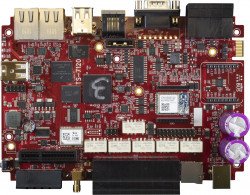
TS-7120
| WARNING: | This product is still in development. This means the documentation and product itself will change several times before the product is deemed ready for Engineering Sampling. Please force-refresh (shift-f5 or ⌘-shift-R on most browsers) to clear your cache when visiting this page to ensure you are viewing the most recent version of this documentation. Of course also please check back often as this information is subject to change. |
 | |
| Product Page | |
| Product Images | |
| Specifications | |
| Documentation | |
|---|---|
| Schematic | |
| FTP Path | |
| Processor | |
| Freescale i.MX6ul 696MHz | |
| i.MX6ul Product Page | |
| CPU Documentation |
Overview
The TS-7120 is an SBC designed for something or other.
Getting Started
A Linux workstation is recommended and assumed for development using this documentation. For users in Windows or OSX, we recommend virtualizing Linux. Most of our platforms run Debian, which is recommended for ease of use if there is no personal distribution preference.
Virtualization
Suggested Linux Distributions
Development using a Windows or OSX system may be possible but is not supported. Development will include accessing drives formatted for Linux and often Linux-based tools.
Getting Console and Powering up
| WARNING: | Be sure to take appropriate Electrostatic Discharge (ESD) precautions. Disconnect the power source before moving, cabling, or performing any set up procedures. Inappropriate handling may cause damage to the device. |
Get console input by plugging a USB type B cable into P4. Connect the host side to a workstation for development. Console can be viewed before or after power is applied. Boot messages will only be printed once the device is powered on.
The cp210x (USB Serial) driver is included in most popular distributions. This will show up as /dev/ttyUSB0. For other operating systems:
The serial console is provided through this port at 115200 baud, 8n1, with no flow control. Picocom is the recommended linux client to use which can be run with the following command:
sudo picocom -b 115200 /dev/ttyUSB0
This will output some serial setting information and then "Terminal ready". Any messages after this point will be from the device via the serial output. The terminal is now ready and power can be applied in order to boot up the device. Power is applied through the power connector, CN4. This accepts an 8-48 VDC input. Alternatively, power may be applied to CN2, which accepts a 5VDC input.
Once power is applied, the device will output information via the console. The first output is from U-Boot:
U-Boot 2016.03-14627-g964baebd6e (Mar 06 2019 - 09:12:01 -0800)

CPU:   Freescale i.MX6UL rev1.2 at 396 MHz
Reset cause: POR
Board: Technologic Systems TS-7120
I2C:   ready
DRAM:  512 MiB
MMC:   FSL_SDHC: 0
Net:   FEC0 [PRIME]
Warning: FEC0 (eth0) using random MAC address - a2:ec:71:14:50:3a

Press Ctrl+C to abort autoboot in 1 second(s)
You may break into U-Boot at this point, by pressing Control+C at your terminal; otherwise, what U-Boot does next depends on the "U-Boot" jumper. If installed, U-Boot will check for USB updates, and then drop to the U-Boot prompt.
Console from Windows
Putty is a small simple client available for download here. Open up Device Manager to determine your console port. See the putty configuration image for more details.


U-Boot
Debian
Debian is a community run Linux distribution. Debian provides tens of thousands of precompiled applications and services. This distribution is known for stability and large community providing support and documentation.
Getting Started with Debian
TS-7120 Jessie Getting started
Debian Networking
From almost any Linux system you can use 'ip' command or the 'ifconfig' and 'route' commands to initially set up the network.
# Bring up the CPU network interface
ifconfig eth0 up

# Or if you're on a baseboard with a second ethernet port, you can use that as:
ifconfig eth1 up

# Set an ip address (assumes 255.255.255.0 subnet mask)
ifconfig eth0 192.168.0.50

# Set a specific subnet
ifconfig eth0 192.168.0.50 netmask 255.255.0.0

# Configure your route.  This is the server that provides your internet connection.
route add default gw 192.168.0.1

# Edit /etc/resolv.conf for your DNS server
echo "nameserver 192.168.0.1" > /etc/resolv.conf
Most networks will offer a DHCP server, an IP address can be obtained from a server with a single command in linux:
Configure DHCP in Debian:
# To setup the default CPU ethernet port
dhclient eth0
# Or if you're on a baseboard with a second ethernet port, you can use that as:
dhclient eth1
# You can configure all ethernet ports for a dhcp response with
dhclient
Systemd provides a networking configuration option to allow for automatic configuration on startup. Systemd-networkd has a number of different configuration files, some of the default examples and setup steps are outlined below.
/etc/systemd/network/eth.network
[Match]
Name=eth*

[Network]
DHCP=yes
To use DHCP to configure DNS via systemd, start and enable the network name resolver service, systemd-resolved:
systemctl start systemd-resolved.service
systemctl enable systemd-resolved.service
ln -s /run/systemd/resolve/resolv.conf /etc/resolv.conf
For a static config create a network configuration for that specific interface.
/etc/systemd/network/eth0.network
[Match]
Name=eth0

[Network]
Address=192.168.0.50/24
Gateway=192.168.0.1
DNS=192.168.0.1
For more information on networking, see Debian and systemd's documentation:
Debian WIFI Client
| Note: | To use WiFi on this product, the wilc3000 driver must be installed. Run "modprobe wilc_spi" before continuing |
If connecting to a WPA/WPA2 network, a wpa_supplicant config file must first be created:
wpa_passphrase yournetwork yournetworkpassphrase > /etc/wpa_supplicant/wpa_supplicant-wlan0.conf
Create the file /lib/systemd/system/wpa_supplicant@.service with these contents
[Unit]
Description=WPA supplicant daemon (interface-specific version)
Requires=sys-subsystem-net-devices-%i.device
After=sys-subsystem-net-devices-%i.device

[Service]
Type=simple
ExecStart=/sbin/wpa_supplicant -c/etc/wpa_supplicant/wpa_supplicant-%I.conf -i%I

[Install]
Alias=multi-user.target.wants/wpa_supplicant@%i.service
Create the file /etc/systemd/network/wlan0.network with:
[Match]
Name=wlan0

[Network]
DHCP=yes
See the systemctl-networkd example for setting a static IP for a network interface. The wlan0.network can be configured the same way as an eth.network.
To enable all of the changes that have been made, run the following commands:
systemctl enable wpa_supplicant@wlan0
systemctl start wpa_supplicant@wlan0
systemctl restart systemd-networkd
Debian WIFI Access Point
First, hostapd needs to be installed in order to manage the access point on the device:
apt-get update && apt-get install hostapd -y
Edit /etc/hostapd/hostapd.conf to include the following lines:
interface=wlan0
driver=nl80211
ssid=YourAPName
channel=1
| Note: | Refer to the kernel's hostapd documentation for more wireless configuration options. |
To start the access point launch hostapd:
hostapd /etc/hostapd/hostapd.conf &
This will start up an access point that can be detected by WIFI clients. A DHCP server will likely be desired to assign IP addresses. Refer to Debian's documentation for more details on DHCP configuration.
Debian Application Development
Debian Jessie Cross Compiling
Debian Jessie previously provided cross compilers via the Emdebian project. However, Emdebian has been unmaintained for a number of years and is no longer able to provide a viable install package. In order to cross compile from a Debian Jessie workstation, a third party cross compiler is required.
A Debian Jessie install on a workstation has the ability to build for the same release on other architectures using Debian binary libraries. A PC, virtual machine, or chroot will need to be used for this. Install Debian Jessie for your workstation here.
From a Debian workstation (not the target), run the following commands to set up the cross compiler. Note that this expects a 64-bit Debian Jessie install on the workstation. 32-bit installations are not supported at this time.
# Run "lsb_release -a" and verify Debian 8.X is returned.  These instructions are not
# expected to work on any other version or distribution.

cd ~
wget http://ftp.embeddedTS.com/ftp/ts-arm-sbc/ts-7553-V2-linux/cross-toolchains/gcc-linaro-4.9-2016.02-x86_64_arm-linux-gnueabihf.tar.xz
# The above toolchain is from Linaro. Other cross compilers can be used but have not been tested.
mkdir cross_compiler
tar xvf gcc-linaro-4.9-2016.02-x86_64_arm-linux-gnueabihf.tar.xz -C ~/cross_compiler
export PATH=$PATH:~/cross_compiler/gcc-linaro-4.9-2016.02-x86_64_arm-linux-gnueabihf/bin/
# The 'export' command needs to be run every time the user logs in. It is possible to add this command to the user's ".bashrc" file
# in their home directory to ensure it is automatically run every time the user is logged in.
su root
dpkg --add-architecture armhf
apt-get update
apt-get install build-essential
This will install a toolchain that can be used with the prefix "arm-linux-gnueabihf-". The standard GCC tools will start with that name, eg "arm-linux-gnueabihf-gcc".
The toolchain can now compile a simple hello world application. Create hello-world.c on the Debian workstation:
#include <stdio.h>
int main(){
    printf("Hello World\n");
}
To compile this:
arm-linux-gnueabihf-gcc hello-world.c -o hello-world
file hello-world
This will return that the binary created is for ARM. Copy this to the target platform to run it there.
Debian Jessie supports multiarch which can install packages designed for other architectures. On workstations this is how 32-bit and 64-bit support is provided. This can also be used to install armhf packages on an x86 based workstation.
This cross compile environment can link to a shared library from the Debian root. The package would be installed in Debian on the workstation to provide headers and ".so" files. This is included in most "-dev" packages. When run on the arm target it will also need a copy of the library installed, but it does not need the -dev package. Note that since the cross compiler used is 3rd party and not directly from Debian, some compile commands that include libraries will need additional arguments to tell the compiler and linker where on the workstation to find the necessary headers and libraries. Usually, the additional arguments will look like the following string, however adjustments may need to be made depending on the application.
-I/usr/include -L/usr/lib/arm-linux-gnueabihf -L/lib/arm-linux-gnueabihf -Wl,-rpath=/usr/lib/arm-linux-gnueabihf,-rpath=/lib/arm-linux-gnueabihf
apt-get install libcurl4-openssl-dev:armhf

# Download the simple.c example from curl:
wget https://raw.githubusercontent.com/bagder/curl/master/docs/examples/simple.c
# After installing the supporting library, curl will link as compiling on the unit.
arm-linux-gnueabihf-gcc -I/usr/include -L/usr/lib/arm-linux-gnueabihf -L/lib/arm-linux-gnueabihf -Wl,-rpath=/usr/lib/arm-linux-gnueabihf,-rpath=/lib/arm-linux-gnueabihf simple.c -o simple -lcurl
Copy the binary to the target platform and run on the target. This can be accomplished with network protocols like NFS, SCP, FTP, etc.
If any created binaries do not rely on hardware support like GPIO or CAN, they can be run using qemu.
# using the hello world example from before:
./hello-world
# Returns Exec format error
apt-get install qemu-user-static
./hello-world
Debian Installing New Software
Debian provides the apt-get system which allows management of pre-built applications. The apt tools require a network connection to the internet in order to automatically download and install new software. The update command will download a list of the current versions of pre-built packages.
Older Debian releases are moved to a different server to indicate it is no longer getting security updates. To download packages for these older distributions, edit /etc/apt/sources.list to only have the following lines:
Jessie:
deb http://archive.debian.org/debian/ jessie main
deb-src http://archive.debian.org/debian/ jessie main
Wheezy:
deb http://archive.debian.org/debian/ wheezy main
deb-src http://archive.debian.org/debian/ wheezy main
After modifying that file, be sure to update the package list:
apt-get update
A common example is installing Java runtime support for a system. Find the package name first with search, and then install it.
root@ts:~# apt-cache search openjdk
jvm-7-avian-jre - lightweight virtual machine using the OpenJDK class library
freemind - Java Program for creating and viewing Mindmaps
icedtea-7-plugin - web browser plugin based on OpenJDK and IcedTea to execute Java applets
default-jdk - Standard Java or Java compatible Development Kit
default-jdk-doc - Standard Java or Java compatible Development Kit (documentation)
default-jre - Standard Java or Java compatible Runtime
default-jre-headless - Standard Java or Java compatible Runtime (headless)
jtreg - Regression Test Harness for the OpenJDK platform
libreoffice - office productivity suite (metapackage)
icedtea-7-jre-jamvm - Alternative JVM for OpenJDK, using JamVM
openjdk-7-dbg - Java runtime based on OpenJDK (debugging symbols)
openjdk-7-demo - Java runtime based on OpenJDK (demos and examples)
openjdk-7-doc - OpenJDK Development Kit (JDK) documentation
openjdk-7-jdk - OpenJDK Development Kit (JDK)
openjdk-7-jre - OpenJDK Java runtime, using Hotspot Zero
openjdk-7-jre-headless - OpenJDK Java runtime, using Hotspot Zero (headless)
openjdk-7-jre-lib - OpenJDK Java runtime (architecture independent libraries)
openjdk-7-source - OpenJDK Development Kit (JDK) source files
uwsgi-app-integration-plugins - plugins for integration of uWSGI and application
uwsgi-plugin-jvm-openjdk-7 - Java plugin for uWSGI (OpenJDK 7)
uwsgi-plugin-jwsgi-openjdk-7 - JWSGI plugin for uWSGI (OpenJDK 7)
In this case you will want the openjdk-7-jre package. Names of packages are on Debian's wiki or the packages site.
With the package name apt-get install can be used to install the prebuilt packages.
apt-get install openjdk-7-jre
# More than one package can be installed at a time.
apt-get install openjdk-7-jre nano vim mplayer
For more information on using apt-get refer to Debian's documentation here.
Debian Setting up SSH
To install ssh, install the package as normal with apt-get:
apt-get install openssh-server
Make sure the device is configured on the network and set a password for the remote user. SSH will not allow remote connections without a password or a valid SSH key pair.
passwd root
| Note: | The default OpenSSH server will not permit root to login via SSH as a security precaution. To allow root to log in via ssh anyway, edit the /etc/ssh/sshd_config file and add the line PermitRootLogin yes in the authentication section. This change will take effect after reboot or after sshd service restart.
|
After this setup it is now possible to connect from a remote PC supporting SSH. On Linux/OS X this is the "ssh" command, or from Windows using a client such as PuTTY.
| Note: | If a DNS server is not present on the target network, it is possible to save time at login by adding "UseDNS no" in /etc/ssh/sshd_config. |
Debian Starting Automatically
A systemd service can be created to start up headless applications. Create a file in /etc/systemd/system/yourapp.service
[Unit]
Description=Run an application on startup

[Service]
Type=simple
ExecStart=/usr/local/bin/your_app_or_script

[Install]
WantedBy=multi-user.target
If networking is a dependency add "After=network.target" in the Unit section. Once you have this file in place add it to startup with:
# Start the app on startup, but will not start it now
systemctl enable yourapp.service

# Start the app now, but doesn't change auto startup
systemctl start yourapp.service
| Note: | See the systemd documentation for in depth documentation on services. |
To start an application on bootup with X11 instead change the x-session-manager. By default the system starts xfce:
root@ts:~# ls -lah /usr/bin/x-session-manager
lrwxrwxrwx 1 root root 35 May 26  2015 /usr/bin/x-session-manager -> /etc/alternatives/x-session-manager
root@ts:~# ls -lah /etc/alternatives/x-session-manager
lrwxrwxrwx 1 root root 19 May 26  2015 /etc/alternatives/x-session-manager -> /usr/bin/startxfce4
The x-session can be modified to only start specified processes. Create the file /usr/bin/mini-x-session with these contents:
#!/bin/bash
matchbox-window-manager -use_titlebar no &

exec xfce4-terminal
You may need to "apt-get install matchbox-window-manager." first. This is a tiny window manager which also has a few flags that simplify embedded use. Now enable this session manager and restart slim to restart x11 and show it now.
chmod a+x /usr/bin/mini-x-session
rm /etc/alternatives/x-session-manager
ln -s /usr/bin/mini-x-session /etc/alternatives/x-session-manager
service slim restart
If the x-session-manager process ever closes x11 will restart. The exec command allows a new process to take over the existing PID. In the above example xfce4-terminal takes over the PID of x-session-manager. If the terminal is closed with commands like exit the slim/x11 processes will restart.
Backup / Restore
MicroSD Card
TS-7120 MicroSD Backup/restore
eMMC
Compile the Kernel
Features
ADC
The TS-7120 has two channels of ADC, and those inputs are available on the CN16-A connector, as 6UL_ADC_0 and 6UL_ADC_1.
The standard linux kernel offers a simple interface to the ADC that does not require any sort of programming to use. For example, to see the "raw" reading from the AN_IN_1 input, type the following command:
WORK IN PROGRESS
cat /sys/bus/iio/devices/iio\:device0/in_voltage4_raw
To convert this raw value to a voltage, it must be multiplied by the "scaling factor", which can be found by typing the following command:
cat /sys/bus/iio/devices/iio\:device0/in_voltage_scale
The result will be in millivolts. If you have the bc utility installed, you can enter the following command:
echo `cat /sys/bus/iio/devices/iio\:device0/in_voltage4_raw` \* `cat /sys/bus/iio/devices/iio\:device0/in_voltage_scale` | bc
To switch to the 10.9V input range, the appropriate enable must be set high. Each input AN_IN_1 through AN_IN_4 has its own enable, EN_ADC1_10V through EN_ADC4_10V, and these are controlled by GPIO #10 through #13. For example, to switch AN_IN_1 to the 10.9V range, run the following command:
tshwctl -a 10 -w 3
Note that the result must now be multiplied by (10.9/2.5). Note also that the input impedance will now be around 2k ohms.
To switch to the 20mA current-loop mode, the appropriate enable must be set high. These are EN_CL_1 through EN_CL_4, and are controlled by GPIO #6 through #9. First select the 2.5V range as follows:
tshwctl -a 10 -w 1
And then set the EN_CL_1 enable high as follows:
tshwctl -a 6 -w 3
| # | 'raw' | 2.5/10.9V Select | 20mA Loop Select |
|---|---|---|---|
| AN_IN_1 | in_voltage4_raw | GPIO 10 | GPIO 6 |
| AN_IN_2 | in_voltage5_raw | GPIO 11 | GPIO 7 |
| AN_IN_3 | in_voltage8_raw | GPIO 12 | GPIO 8 |
| AN_IN_4 | in_voltage9_raw | GPIO 13 | GPIO 9 |
| Note: | The four ADC inputs use the CPU ADC inputs 4,5,8, and 9, corresponding with the 'raw' entries in the above table. |
Bluetooth
The Wi-Fi option for this platform also includes a Bluetooth 5.0 LE module. Support for Bluetooth is provided by the BlueZ project. BlueZ has support for many different profiles for HID, A2DP, and many more. Refer to the BlueZ documentation for more information. Please see our BLE Examples page for information on installing the latest BlueZ release, getting started, and using demo applications.
Both Wi-Fi and Bluetooth can be active at the same time on this platform. Note however, that either the Wi-Fi interface needs to be not brought up if Wi-Fi is unused, or it needs to actively connect to an access point or act as an access point. The Bluetooth module can be activated with the following commands:
For Bluez versions found on Debian Stretch and below:
# Enable Bluetooth, and load the firmware
echo BT_POWER_UP > /dev/wilc_bt
sleep 1
echo BT_FW_CHIP_WAKEUP > /dev/wilc_bt
sleep 1
echo BT_DOWNLOAD_FW > /dev/wilc_bt
sleep 1

# Attach the BLE device to the system, increase the baud, and enable flow control
hciattach /dev/ttyS6 any 115200 noflow
sleep 1
hcitool cmd 0x3F 0x0053 00 10 0E 00 01
stty -F /dev/ttyS6 921600 crtscts
For newer versions of BlueZ found on Debian Buster or newer:
echo BT_POWER_UP > /dev/wilc_bt
sleep 1
echo BT_FW_CHIP_WAKEUP > /dev/wilc_bt
sleep 1
echo BT_DOWNLOAD_FW > /dev/wilc_bt
sleep 1

btattach -N -B /dev/ttyS6 -S 115200 &
sleep 1
hcitool cmd 0x3F 0x0053 00 10 0E 00 01
kill %1 # This terminates the above btattach command
sleep 1
btattach -B /dev/ttyS6 -S 921600 &
At this point, the device is running at 921600 baud with flow control, and is fully set up ready to be controlled by various components of BlueZ tools. For example, to do a scan of nearby devices:
bluetoothctl
power on
scan on
This will return a list of devices such as:
root@ts-imx6ul:~# bluetoothctl
Agent registered
[CHG] Controller F8:F0:05:XX:XX:XX Pairable: yes
[bluetooth]# power on
Changing power on succeeded
[CHG] Controller F8:F0:05:XX:XX:XX Powered: yes
[bluetooth]# scan on
Discovery started
[CHG] Controller F8:F0:05:XX:XX:XX Discovering: yes
[NEW] Device 51:DD:C0:XX:XX:XX Device_Name
[NEW] Device 2A:20:E2:XX:XX:XX Device_Name
[CHG] Device 51:DD:C0:XX:XX:XX RSSI: -93
[CHG] Device 51:DD:C0:XX:XX:XX RSSI: -82
[NEW] Device E2:08:B5:XX:XX:XX Device_Name
[CHG] Device 51:DD:C0:XX:XX:XX RSSI: -93
[CHG] Device 2A:20:E2:XX:XX:XX RSSI: -94
[NEW] Device 68:62:92:XX:XX:XX Device_Name
[NEW] Device 68:79:12:XX:XX:XX Device_Name
[bluetooth]# quit
Please note that the Bluetooth module requires the modem control lines CTS and RTS as flow control when running at higher baud rates. It is possible to run the module at the initial 115200 baud if the flow control lines are unwanted.
The module supports some other commands as well:
# Allow the BT chip to enter sleep mode
echo BT_FW_CHIP_ALLOW_SLEEP > /dev/wilc_bt

# Power down the BT radio when not in use
echo BT_POWER_DOWN > /dev/wilc_bt
CAN
The i.MX6UL includes 2 CAN controllers which support the SocketCAN interface, and these are presented on the CN32 connector and on the CN17 connector (custom populations may differ).
Before proceeding with the examples, see the Kernel's CAN documentation here.
This board comes preinstalled with can-utils which can be used to communicate over a CAN network without writing any code. The candump utility can be used to dump all data on the network
## First, set the baud rate and bring up the device:
ip link set can0 type can bitrate 250000
ip link set can0 up

## Dump data & errors:
candump can0 &

## Send the packet with:
#can_id = 0x7df
#data 0 = 0x3
#data 1 = 0x1
#data 2 = 0x0c
cansend can0 -i 0x7DF 0x3 0x1 0x0C
## Some versions of cansend use a different syntax.  If the above
## commands gives an error, try this instead:
#cansend can0 7DF#03010C
The above example packet is designed to work with the Ozen Elektronik myOByDic 1610 ECU simulator to read the RPM speed. In this case, the ECU simulator would return data from candump with:
 <0x7e8> [8] 04 41 0c 60 40 00 00 00
 <0x7e9> [8] 04 41 0c 60 40 00 00 00
In the output above, columns 6 and 7 are the current RPM value. This shows a simple way to prove out the communication before moving to another language.
The following example sends the same packet and parses the same response in C:
#include <stdio.h>
#include <pthread.h>
#include <net/if.h>
#include <string.h>
#include <unistd.h>
#include <net/if.h>
#include <sys/ioctl.h>
#include <assert.h>
#include <linux/can.h>
#include <linux/can/raw.h>

int main(void)
{
	int s;
	int nbytes;
	struct sockaddr_can addr;
	struct can_frame frame;
	struct ifreq ifr;
	struct iovec iov;
	struct msghdr msg;
	char ctrlmsg[CMSG_SPACE(sizeof(struct timeval)) + CMSG_SPACE(sizeof(__u32))];
	char *ifname = "can0";

	if((s = socket(PF_CAN, SOCK_RAW, CAN_RAW)) < 0) {
		perror("Error while opening socket");
		return -1;
	}

	strcpy(ifr.ifr_name, ifname);
	ioctl(s, SIOCGIFINDEX, &ifr);
	addr.can_family  = AF_CAN;
	addr.can_ifindex = ifr.ifr_ifindex;

	if(bind(s, (struct sockaddr *)&addr, sizeof(addr)) < 0) {
		perror("socket");
		return -2;
	}

 	/* For the ozen myOByDic 1610 this requests the RPM guage */
	frame.can_id  = 0x7df;
	frame.can_dlc = 3;
	frame.data[0] = 3;
	frame.data[1] = 1;
	frame.data[2] = 0x0c;

	nbytes = write(s, &frame, sizeof(struct can_frame));
	if(nbytes < 0) {
		perror("write");
		return -3;
	}

	iov.iov_base = &frame;
	msg.msg_name = &addr;
	msg.msg_iov = &iov;
	msg.msg_iovlen = 1;
	msg.msg_control = &ctrlmsg;
	iov.iov_len = sizeof(frame);
	msg.msg_namelen = sizeof(struct sockaddr_can);
	msg.msg_controllen = sizeof(ctrlmsg);
	msg.msg_flags = 0;

	do {
		nbytes = recvmsg(s, &msg, 0);
		if (nbytes < 0) {
			perror("read");
			return -4;
		}

		if (nbytes < (int)sizeof(struct can_frame)) {
			fprintf(stderr, "read: incomplete CAN frame\n");
		}
	} while(nbytes == 0);

	if(frame.data[0] == 0x4)
		printf("RPM at %d of 255\n", frame.data[3]);

	return 0;
}
See the Kernel's CAN documentation here. Other languages have bindings to access CAN such as Python, Java using JNI.
In production use of CAN we also recommend setting a restart-ms for each active CAN port.
ip link set can0 type can restart-ms 100
This allows the CAN bus to automatically recover in the event of a bus-off condition.
CPU
DMX
Three pins (1, 2, and 7) on the RJ-45 connector (CN8) are allocated as a DMX-512 controller. They are in the same position on the connector as in standard DMX. However, the remaining pins are allocated as an RS-232 port, in the positions specified by EIA/TIA-561. The two interfaces must not be used at the same time without an adapter cable.
eMMC
Ethernet Ports
FPGA
FPGA Registers
The TS-7120 FPGA is connected to the CPU over the WEIM bus. This provides 8-bit, 16-bit, or 32-bit access to the FPGA mapped at 0x5000_0000.
For example, to read the syscon 0x0:
peekpoke 32 0x50004000
| Offset | Description |
|---|---|
| 0x00 | 16550 #0 |
| 0x10 | 16550 #1 |
| 0x20 | 16550 #2 |
| 0x30 | 16550 #3 |
| 0x40 | 16550 #4 |
| 0x50 | 16550 #5 |
| 0x60 | 16550 #6 |
| 0x70 | 16550 #7 |
| 0x80 | 16550 #8 |
| 0x100 | Opencore SPI controller #0 |
| 0x120 | Opencore SPI controller #1 |
| 0x140 | Opencore SPI controller #2 |
| 0x280 | TS SDcore |
| 0x4000 | Syscon |
Syscon
| Offset | Bits | Description | |||||||
|---|---|---|---|---|---|---|---|---|---|
| 0x0 | 31:0 | Model ID | |||||||
| 0x4 | 31:0 | FPGA_REV_CRC32 | |||||||
| 0x08 (read) | 31:20 | Reserved | |||||||
| 19 | Toggles when data_valid ASMI output is 1 | ||||||||
| 18 | Illegal Erase | ||||||||
| 17 | Illegal Write | ||||||||
| 16 | ASMI Busy | ||||||||
| 15:8 | ASMI Status out | ||||||||
| 7:0 | ASMI Data out | ||||||||
| 0x08 (write) | 31 | Reserved | |||||||
| 30:29 |
| ||||||||
| 28:8 | ASMI Address | ||||||||
| 7:0 | ASMI data in | ||||||||
| 0x0c | 31:0 | Scratch register | |||||||
| 0x10 | 15:0 | DIO bank 0 Data Set [1] | |||||||
| 0x12 | 15:0 | DIO bank 0 Output Enable Set [2] | |||||||
| 0x14 | 15:0 | DIO bank 0 Data Clear [2] | |||||||
| 0x16 | 15:0 | DIO bank 0 Output Enable clear [2] | |||||||
| 0x18 | 31:0 | Reserved | |||||||
| 0x1c | 31:16 | Current loop PWM #1 | |||||||
| 15:0 | Current loop PWM #0 | ||||||||
| 0x24 | 31:0 | IRQ Status | |||||||
| 0x28 | 31:16 | ADC 1 | |||||||
| 15:0 | ADC 0 | ||||||||
| 0x2c | 31:16 | ADC 3 | |||||||
| 15:0 | ADC 2 | ||||||||
| 0x30 | 31:16 | ADC 5 | |||||||
| 15:0 | ADC 4 | ||||||||
| 0x34 | 31:16 | ADC 7 | |||||||
| 15:0 | ADC 6 | ||||||||
| 0x3c | 31:19 | Reserved | |||||||
| 18 | mikro_pwm_en [3] | ||||||||
| 17 | hart_mode [4] | ||||||||
| 16 | an_67_sel [5] | ||||||||
| 15:0 | mikro_pwm | ||||||||
| 0x40 | 15:0 | DIO Bank 1 Data Set [1] | |||||||
| 0x42 | 15:0 | DIO bank 1 Output Enable Set [2] | |||||||
| 0x44 | 15:0 | DIO bank 1 Data Clear [2] | |||||||
| 0x46 | 15:0 | DIO bank 1 Output Enable clear [2] | |||||||
| 0x48 | 31:0 | IRQ mask |
- ↑ 1.0 1.1 On a write, this sets the output value. On a read this reads the current state of the pin.
- ↑ 2.0 2.1 2.2 2.3 2.4 2.5 This register is write only, and reading it back may not reflect the status value that is written.
- ↑ If PWM is not enabled this pin as available as a GPIO. When this is enabled only the PWM value is used and the corresponding GPIO bit is ignored
- ↑ 0 = all 4 HART channels RX. 1 = RX on channels 0,1 and TX on channels 2,3
- ↑ 0=STC_AN_6 is used as ADC 7. 1=STC_AN_7 is used as ADC7.
FPGA DIO Banks
| Bank | IO | Description |
|---|---|---|
| 0 | 15 | sys_reset_padn |
| 14 | en_blue_led_pad | |
| 13 | silab_dat_pad | |
| 12 | silab_clk_pad | |
| 11 | dio_14_pad | |
| 10 | dio_13_pad | |
| 9 | dio_12_pad | |
| 8 | dio_11_pad | |
| 7 | dio_10_pad | |
| 6 | dio_9_pad | |
| 5 | dio_8_pad | |
| 4 | dio_7_pad | |
| 3 | dio_6_pad | |
| 2 | dio_5_pad | |
| 1 | dio_4_pad | |
| 0 | dio_2_pad | |
| 1 | 15 | wifi_reset_padn |
| 14 | en_ls_out_1_pad | |
| 13 | en_emmc_3v3_padn | |
| 12 | en_gps_3v3_padn | |
| 11 | en_nimbel_4v_pad | |
| 10 | en_wifi_pwr_pad | |
| 9 | en_ls_out_0_pad | |
| 8 | en_xbee_usb_pad | |
| 7 | en_hs_sw_pad | |
| 6 | en_dig_in_2_3_pad | |
| 5 | en_can_xcvr_padn | |
| 4 | en_nimbel_3v3_pad | |
| 3 | en_poe_padn | |
| 2 | en_an_5v_pad | |
| 1 | en_dig_in_0_1_pad | |
| 0 | mikro_reset_padn |
FPGA IRQs
| Bit | Description |
|---|---|
| 31:17 | Reserved |
| 16 | cpu_touch_irq IRQ |
| 15 | wifi_irq |
| 14 | gyro_int |
| 13 | mikro_int |
| 12 | TS SDcore |
| 11 | Opencore SPI controller #2 |
| 10 | Opencore SPI Controller #1 |
| 9 | Opencore SPI Controller #0 |
| 8 | UART #8 IRQ |
| 7 | UART #7 IRQ |
| 6 | UART #6 IRQ |
| 5 | UART #5 IRQ |
| 4 | UART #4 IRQ |
| 3 | UART #3 IRQ |
| 2 | UART #2 IRQ |
| 1 | UART #1 IRQ |
| 0 | UART #0 IRQ |
FRAM
SPI FRAM
This platform supports a soldered-down, non-volatile Ferroelectric RAM (FRAM) device. The Cypress FM25L16B is a 2 KiB FRAM device in a configuration not unlike an SPI EEPROM. The nature of FRAM means it is non-volatile, incredibly fast to write, and is specified with 100 trillion read/write cycles (per each of the 256 sequential 8 byte rows) with a 150 year data retention at temperatures below 65 °C. The device is connected to Linux and presents itself as a flat file that can be read and written like any standard Linux file.
The EEPROM file can be found at /sys/class/spi_master/spi32766/spi32766.0/eeprom, and should be accessed like a normal file to write and read data in the FRAM.
GPIO
RELAYS
The TS-7120 has six on-board relays. The first four relays have normally-open and normally-closed contacts brought out on the terminal block CN32-A. The remaining two have normally-open contacts only, also brought out on CN32-A.
The relays may be controlled via the sysfs, as shown in the example below.
# first step is to configure GPIO for the six control lines
echo 132 > /sys/class/gpio/export
echo out > /sys/class/gpio/gpio132/direction
echo 133 > /sys/class/gpio/export
echo out > /sys/class/gpio/gpio133/direction
echo 134 > /sys/class/gpio/export
echo out > /sys/class/gpio/gpio134/direction
echo 135 > /sys/class/gpio/export
echo out > /sys/class/gpio/gpio135/direction
echo 136 > /sys/class/gpio/export
echo out > /sys/class/gpio/gpio136/direction
echo 137 > /sys/class/gpio/export
echo out > /sys/class/gpio/gpio137/direction

# turn on relay #1
echo 1 > /sys/class/gpio/gpio132/value

#turn it off again
echo 0 > /sys/class/gpio/gpio132/value
GPS
The TS-7120 has an on-board Telit SL869 GPS receiver. An SMA female connector is provided for the connection of an antenna.
Before it can be used, power to the GPS receiver must be enabled by setting GPIO #188 high, as shown below:
echo 188 > /sys/class/gpio/export
echo out > /sys/class/gpio/gpio188/direction
echo 1 > /sys/class/gpio/gpio188/value
The GPS receiver may then be accessed via the /dev/ttyS16 uart, at a default baud rate of 9600.
HART
The TS-7120 provides four HART MODEMs for 1200 baud FSK signaling over its current-loop channels.
By default, all four MODEMs operate on their respective current-loop receiver pins (HART_0 through HART_3 on CN-16B). When the upper two channels are configured as current loop transmitters (FPGA hart_mode=1), MODEMs 2 and 3 send and receive over the current loop transmitter pins (CL_TX0 and CL_TX1 on CN-16A) instead of over their respective current loop receiver pins.
IMU
This board features an ST ISM330DLC, which provides both a 3-axis accelerometer and a gyroscope. The accelerometer has an acceleration range of ±2/±4/±8/±16 g. The gyroscope has a selectable angular range of ±125/±250/±500/±1000/±2000 dps.
Linux provides access to both as part of the IIO subsystem (via iio-tools and libiio). They are accessed as ism330dlc_accel and ism330dlc_gyro, respectively.
ST ISM330 Accelerometer
This platform features an ST accelerometer / gyroscope. The accelerometer has an acceleration range of ±2/±4/±8/±16 g.
Early units were built using the "ism330dlc", and newer units are built using the "ism330dhcx". These are functionally the same and provide the same channels and performance, but IIO requires you to specify the part number. Our example python/c code will show how to work with either.
The accelerometer is accessed through IIO with channels:
- accel_x
- accel_y
- accel_z
- timestamp
For example:
# ISM330DHCX
iio_attr -c ism330dhcx_accel accel_x
iio_attr -c ism330dhcx_accel accel_y
iio_attr -c ism330dhcx_accel accel_z
# ISM330DLC
iio_attr -c ism330dlc_accel accel_x
iio_attr -c ism330dlc_accel accel_y
iio_attr -c ism330dlc_accel accel_z
The below examples will be written for the ism330dhcx_accel, but if this fails instead use the ism330dlc_accel device. These commands will provide a single sample of all of the values:
root@tsimx6ul:~# iio_attr -c ism330dhcx_accel accel_x
dev 'ism330dhcx_accel', channel 'accel_x' (input), attr 'injection_raw', ERROR: Permission denied (-13)
dev 'ism330dhcx_accel', channel 'accel_x' (input), attr 'raw', value '-183'
dev 'ism330dhcx_accel', channel 'accel_x' (input), attr 'scale', value '0.000598'
dev 'ism330dhcx_accel', channel 'accel_x' (input), attr 'scale_available', value '0.000598 0.001196 0.002392 0.004785'
root@tsimx6ul:~# iio_attr -c ism330dhcx_accel accel_y
dev 'ism330dhcx_accel', channel 'accel_y' (input), attr 'injection_raw', ERROR: Permission denied (-13)
dev 'ism330dhcx_accel', channel 'accel_y' (input), attr 'raw', value '-292'
dev 'ism330dhcx_accel', channel 'accel_y' (input), attr 'scale', value '0.000598'
dev 'ism330dhcx_accel', channel 'accel_y' (input), attr 'scale_available', value '0.000598 0.001196 0.002392 0.004785'
root@tsimx6ul:~# iio_attr -c ism330dhcx_accel accel_z
dev 'ism330dhcx_accel', channel 'accel_z' (input), attr 'injection_raw', ERROR: Permission denied (-13)
dev 'ism330dhcx_accel', channel 'accel_z' (input), attr 'raw', value '16491'
dev 'ism330dhcx_accel', channel 'accel_z' (input), attr 'scale', value '0.000598'
dev 'ism330dhcx_accel', channel 'accel_z' (input), attr 'scale_available', value '0.000598 0.001196 0.002392 0.004785'
To get the real world value, multiply the scale * the raw value. In this case:
- X: -0.109434 g
- Y: -0.174616 g
- Z: 9.861618 g
The default scale is ±2, but ±2/±4/±8/±16 can be selected by setting the scale:
dev 'ism330dhcx_accel', channel 'accel_z' (input), attr 'scale', value '0.000598'
dev 'ism330dhcx_accel', channel 'accel_z' (input), attr 'scale_available', value '0.000598 0.001196 0.002392 0.004785'
To set ±4, you would write the second available scale:
iio_attr -c ism330dhcx_accel accel_x scale 0.001196
The scale values are not independent on this device, and setting x/y/z will set the scale for all 3.
This driver also supports pulling continuous samples using the buffer interface. These can be accessed using iio_readdev:
iio_readdev ism330dhcx_accel -T 0 -s 128 > samples.bin
The format of this file is specified with iio_attr:
root@tsimx6ul:~# iio_attr -c ism330dhcx_accel
dev 'ism330dhcx_accel', channel 'accel_x' (input, index: 0, format: le:S16/16>>0), found 4 channel-specific attributes
dev 'ism330dhcx_accel', channel 'accel_y' (input, index: 1, format: le:S16/16>>0), found 4 channel-specific attributes
dev 'ism330dhcx_accel', channel 'accel_z' (input, index: 2, format: le:S16/16>>0), found 4 channel-specific attributes
dev 'ism330dhcx_accel', channel 'timestamp' (input, index: 3, format: le:S64/64>>0), found 0 channel-specific attributes
The samples are padded to the nearest 8-bytes, so this means the binary format is:
| Bits | Description |
|---|---|
| 15:0 | accel_x, little endian, signed |
| 15:0 | accel_y, little endian, signed |
| 15:0 | accel_z, little endian, signed |
| 63:0 | timestamp, little endian, signed |
| 15:0 | Padding |
The unix utility hexdump supports formatting options which can parse these fields:
root@tsimx6ul:~# hexdump samples.bin --format '1/2 "X:%d " 1/2 "Y:%d " 1/2 "Z:%d " 1/8 "TS:%d" 1/2 "" "\n"' | head -n 4
X:-95 Y:-163 Z:8221 TS:200185381271666439
X:-107 Y:-147 Z:8248 TS:200190332264480519
X:-100 Y:-155 Z:8263 TS:200195283888013063
X:-95 Y:-159 Z:8253 TS:200200232540667655
This gives the raw values which can then be multiplied by the scale to get the real world value.
The IIO library can also be used to fill buffers with samples for processing. For example:
#!/usr/bin/env python3

import struct
import iio

ctx = iio.Context('local:')
ctx.set_timeout(0)
dev = ctx.find_device('ism330dhcx_accel') or ctx.find_device('ism330dlc_accel')

with open(f'/sys/bus/iio/devices/{dev.id}/sampling_frequency', 'w') as f:
	f.write(f"833.000")

for chan_name in ["accel_x", "accel_y", "accel_z"]:
	chn = dev.find_channel(chan_name)
	chn.enabled = True

# We will request 64 samples at a time
buffer = iio.Buffer(dev, 64, False)
# sample size (3x 16-bit signed data)
sample_size = 6
# Refill and process the buffer
buffer.refill()
data = buffer.read()
for i in range(0, len(data), sample_size):
	if i + sample_size <= len(data):
		x, y, z = struct.unpack('<hhh', data[i:i+sample_size])
		print(f'  accel_x={x}, accel_y={y}, accel_z={z}')

for chn in dev.channels:
	chn.enabled = False
This can also be done using the C library:
#include <stdio.h>
#include <stdlib.h>
#include <string.h>
#include <iio.h>

#define NUM_CHANNELS 3
#define SAMPLE_SIZE 6 // 3x 16-bit signed data (2 bytes per axis)

void process_samples(struct iio_buffer *buffer, size_t sample_size) {
    char *data = iio_buffer_start(buffer);
    size_t buffer_size = iio_buffer_end(buffer) - iio_buffer_start(buffer);
    int16_t x, y, z;

    for (size_t i = 0; i < buffer_size; i += sample_size) {
        memcpy(&x, &data[i], sizeof(x));
        memcpy(&y, &data[i + sizeof(x)], sizeof(y));
        memcpy(&z, &data[i + 2 * sizeof(x)], sizeof(z));
        printf("accel_x=%d, accel_y=%d, accel_z=%d\n", x, y, z);
    }
}

int main() {
    struct iio_context *ctx;
    struct iio_device *dev;
    struct iio_channel *channels[NUM_CHANNELS];
    struct iio_buffer *buffer;
    const char *channel_names[NUM_CHANNELS] = { "accel_x", "accel_y", "accel_z" };

    // Create context and find device
    ctx = iio_create_local_context();
    if (!ctx || !(dev = iio_context_find_device(ctx, "ism330dhcx_accel")) &&
        !(dev = iio_context_find_device(ctx, "ism330dlc_accel"))) {
        fprintf(stderr, "Unable to create context or find device\n");
        iio_context_destroy(ctx);
        return 1;
    }

    // Enable channels and set sampling frequency
    for (int i = 0; i < NUM_CHANNELS; i++) {
        channels[i] = iio_device_find_channel(dev, channel_names[i], false);
        if (!channels[i] || iio_channel_attr_write(channels[i], "sampling_frequency", "833.000") < 0) {
            fprintf(stderr, "Unable to find or configure channel %s\n", channel_names[i]);
            iio_context_destroy(ctx);
            return 1;
        }
        iio_channel_enable(channels[i]);
    }

    // Create buffer and process samples
    buffer = iio_device_create_buffer(dev, 64, false);
    if (!buffer || iio_buffer_refill(buffer) < 0) {
        fprintf(stderr, "Unable to create or refill buffer\n");
        iio_context_destroy(ctx);
        return 1;
    }

    process_samples(buffer, SAMPLE_SIZE);

    // Cleanup
    iio_buffer_destroy(buffer);
    iio_context_destroy(ctx);

    return 0;
}
ST ISM330 Gyroscope
This platform features an ST accelerometer / gyroscope. The gyroscope has a selectable angular range of ±125/±250/±500/±1000/±2000 dps
Early units were built using the "ism330dlc", and newer units are built using the "ism330dhcx". These are functionally the same and provide the same channels and performance, but IIO requires you to specify the part number. Our example python/c code will show how to work with either.
The gyroscope is accessed through IIO with channels:
- anglvel_x
- anglvel_y
- anglvel_z
- timestamp
For example:
# ISM330DHCX
iio_attr -c ism330dhcx_gyro anglvel_x
iio_attr -c ism330dhcx_gyro anglvel_y
iio_attr -c ism330dhcx_gyro anglvel_z
# ISM330DLC
iio_attr -c ism330dlc_gyro anglvel_x
iio_attr -c ism330dlc_gyro anglvel_y
iio_attr -c ism330dlc_gyro anglvel_z
root@tsimx6ul:~# iio_attr -c ism330dhcx_gyro anglvel_x
dev 'ism330dhcx_gyro', channel 'anglvel_x' (input), attr 'raw', value '2359'
dev 'ism330dhcx_gyro', channel 'anglvel_x' (input), attr 'scale', value '0.000153'
dev 'ism330dhcx_gyro', channel 'anglvel_x' (input), attr 'scale_available', value '0.000153 0.000305 0.000611 0.001222'
root@tsimx6ul:~# iio_attr -c ism330dhcx_gyro anglvel_y
dev 'ism330dhcx_gyro', channel 'anglvel_y' (input), attr 'raw', value '-1667'
dev 'ism330dhcx_gyro', channel 'anglvel_y' (input), attr 'scale', value '0.000153'
dev 'ism330dhcx_gyro', channel 'anglvel_y' (input), attr 'scale_available', value '0.000153 0.000305 0.000611 0.001222'
root@tsimx6ul:~# iio_attr -c ism330dhcx_gyro anglvel_z
dev 'ism330dhcx_gyro', channel 'anglvel_z' (input), attr 'raw', value '2761'
dev 'ism330dhcx_gyro', channel 'anglvel_z' (input), attr 'scale', value '0.000153'
dev 'ism330dhcx_gyro', channel 'anglvel_z' (input), attr 'scale_available', value '0.000153 0.000305 0.000611 0.001222'
This shows a snapshot of the x, y, z values. To get the real world value, multiply the scale * the raw value. In this case:
- X: 0.360927 dps
- Y: -0.255051 dps
- Z: 0.422433 dps
The default scale is ±250, but ±250/±500/±1000/±2000 can be selected by setting the scale:
dev 'ism330dhcx_gyro', channel 'anglvel_z' (input), attr 'scale', value '0.000153'
dev 'ism330dhcx_gyro', channel 'anglvel_z' (input), attr 'scale_available', value '0.000153 0.000305 0.000611 0.001222'
To set ±1000, you would write the third available scale:
iio_attr -c ism330dhcx_gyro anglvel_z scale 0.000611
The scale values are not independent on this device, and setting x/y/z will set the scale for all 3.
This driver also supports pulling continuous samples using the buffer interface. These can be accessed using iio_readdev:
iio_readdev ism330dhcx_gyro -T 0 -s 128 > samples.bin
The format of this file is specified with iio_attr:
root@tsimx6ul:~# iio_attr -c ism330dhcx_gyro
dev 'ism330dlc_gyro', channel 'anglvel_x' (input, index: 0, format: le:S16/16>>0), found 3 channel-specific attributes
dev 'ism330dlc_gyro', channel 'anglvel_y' (input, index: 1, format: le:S16/16>>0), found 3 channel-specific attributes
dev 'ism330dlc_gyro', channel 'anglvel_z' (input, index: 2, format: le:S16/16>>0), found 3 channel-specific attributes
dev 'ism330dlc_gyro', channel 'timestamp' (input, index: 3, format: le:S64/64>>0), found 0 channel-specific attributes
The samples are padded to the nearest 8-bytes, so this means the binary format is:
| Bits | Description |
|---|---|
| 15:0 | anglvel_x, little endian, signed |
| 15:0 | anglvel_y, little endian, signed |
| 15:0 | anglvel_z, little endian, signed |
| 63:0 | timestamp, little endian, signed |
| 15:0 | Padding |
The unix utility hexdump supports formatting options which can parse these fields into their raw values:
root@tsimx6ul:~# hexdump samples.bin --format '1/2 "X:%d " 1/2 "Y:%d " 1/2 "Z:%d " 1/8 "TS:%d" 1/2 "" "\n"' | head -n 40
X:-58 Y:-199 Z:24 TS:419695978925948679
X:-67 Y:-196 Z:29 TS:419701023781322503
X:-64 Y:-197 Z:28 TS:419705968690298631
X:-58 Y:-203 Z:29 TS:419711008204553991
The IIO library can also be used to fill buffers with samples for processing. For example:
#!/usr/bin/env python3

import struct
import iio

ctx = iio.Context('local:')
ctx.set_timeout(0)
dev = ctx.find_device('ism330dhcx_gyro') or ctx.find_device('ism330dlc_gyro')

with open(f'/sys/bus/iio/devices/{dev.id}/sampling_frequency', 'w') as f:
	f.write(f"833.000")

for chan_name in ["anglvel_x", "anglvel_y", "anglvel_z"]:
	chn = dev.find_channel(chan_name)
	chn.enabled = True

# We will request 64 samples at a time
buffer = iio.Buffer(dev, 64, False)
# sample size (3x 16-bit signed data)
sample_size = 6
# Refill and process the buffer
buffer.refill()
data = buffer.read()
for i in range(0, len(data), sample_size):
	if i + sample_size <= len(data):
		x, y, z = struct.unpack('<hhh', data[i:i+sample_size])
		print(f'  anglvel_x={x}, anglvel_y={y}, anglvel_z={z}')

for chn in dev.channels:
	chn.enabled = False
This can also be done using the C library:
#include <stdio.h>
#include <stdlib.h>
#include <string.h>
#include <iio.h>

#define NUM_CHANNELS 3
#define SAMPLE_SIZE 6 // 3x 16-bit signed data (2 bytes per axis)

void process_samples(struct iio_buffer *buffer, size_t sample_size) {
    char *data = iio_buffer_start(buffer);
    size_t buffer_size = iio_buffer_end(buffer) - iio_buffer_start(buffer);
    int16_t x, y, z;

    for (size_t i = 0; i < buffer_size; i += sample_size) {
        memcpy(&x, &data[i], sizeof(x));
        memcpy(&y, &data[i + sizeof(x)], sizeof(y));
        memcpy(&z, &data[i + 2 * sizeof(x)], sizeof(z));
        printf("anglvel_x=%d, anglvel_y=%d, anglvel_z=%d\n", x, y, z);
    }
}

int main() {
    struct iio_context *ctx;
    struct iio_device *dev;
    struct iio_channel *channels[NUM_CHANNELS];
    struct iio_buffer *buffer;
    const char *channel_names[NUM_CHANNELS] = { "anglvel_x", "anglvel_y", "anglvel_z" };

    // Create context and find device
    ctx = iio_create_local_context();
    if (!ctx || !(dev = iio_context_find_device(ctx, "ism330dhcx_gyro")) &&
        !(dev = iio_context_find_device(ctx, "ism330dlc_gyro"))) {
        fprintf(stderr, "Unable to create context or find device\n");
        iio_context_destroy(ctx);
        return 1;
    }

    // Enable channels and set sampling frequency
    for (int i = 0; i < NUM_CHANNELS; i++) {
        channels[i] = iio_device_find_channel(dev, channel_names[i], false);
        if (!channels[i] || iio_channel_attr_write(channels[i], "sampling_frequency", "833.000") < 0) {
            fprintf(stderr, "Unable to find or configure channel %s\n", channel_names[i]);
            iio_context_destroy(ctx);
            return 1;
        }
        iio_channel_enable(channels[i]);
    }

    // Create buffer and process samples
    buffer = iio_device_create_buffer(dev, 64, false);
    if (!buffer || iio_buffer_refill(buffer) < 0) {
        fprintf(stderr, "Unable to create or refill buffer\n");
        iio_context_destroy(ctx);
        return 1;
    }

    process_samples(buffer, SAMPLE_SIZE);

    // Cleanup
    iio_buffer_destroy(buffer);
    iio_context_destroy(ctx);

    return 0;
}
Interrupts
Jumpers
The TS-7120 has a set of jumpers located near the relays on the SBC.
These jumpers control a number of aspects of the TS-7120's behavior. The jumpers are labeled on the silkscreen rather than numbered:
| Label | Description |
|---|---|
| NO Charge | When jumper is set, disable charging of the SuperCaps. Beneficial for early development and testing. |
| CAN1 | When jumper is set, adds a 120 ohm termination resistor across CAN1 H and L pins. |
| 485 | When jumper is set, adds a 120 ohm termination resistor across RS-485 + and - pins. |
LEDs
The red and green LEDs can be controlled from userspace after bootup using the sysfs LED interface. For example, to turn on the red LED:
echo 1 > /sys/class/leds/red-led/brightness
The following LEDs are available on this system:
- red-led
- green-led
A number of triggers are also available, including timers, disk activity, and heartbeat. These allow the LEDs to represent various system activities as they occur. See the kernel LED documentation for more information on triggers and general use of LED class devices.
Magnetometer
This board includes an ST IIS2MDCTR 3-axis magnetometer, which has a magnetic field dynamic range of ±50 gauss (16 bits of precision at up to 150 Hz).
The magnetometer is accessed through Linux's industrial I/O (IIO) subsystem as lis2mdl with channels:
- magn_x
- magn_y
- magn_z
- timestamp
For example:
root@tsimx6ul:~# iio_attr -c lis2mdl -c magn_x
dev 'lis2mdl', channel 'magn_x' (input), attr 'raw', value '630'
dev 'lis2mdl channel 'magn_x' (input), attr 'scale', value '0.001500'
root@tsimx6ul:~# iio_attr -c lis2mdl -c magn_y
dev 'lis2mdl channel 'magn_y' (input), attr 'raw', value '-165'
dev 'lis2mdl channel 'magn_y' (input), attr 'scale', value '0.001500'
root@tsimx6ul:~# iio_attr -c lis2mdl -c magn_z
dev 'lis2mdl channel 'magn_z' (input), attr 'raw', value '9'
dev 'lis2mdl channel 'magn_z' (input), attr 'scale', value '0.001500'
This shows a snapshot of the x, y, z values. To get the measured field strength along each axis, multiply the scale by the raw value to get the actual reading in milligauss. In the above example:
- X: 0.945 mG (milligauss)
- Y: -0.2475 mG
- Z: 0.0135 mG
MicroSD Card Interface
The TS-7120 has a micro-SD connector. When a micro-SD card is installed, it shows up as /dev/tssdcarda; and if it contains valid partitions, these will appear as /dev/tssdcarda1, /dev/tssdcarda2, /dev/tssdcarda3, and /dev/tssdcarda4 (depending on how the card is partitioned). Any partition with a valid filesystem may be mounted as shown below:
## Make sure the driver is loaded first
modprobe tssdcard

## Mount the first partition
mount /dev/tssdcarda1 /mnt/sd/
OBD-II
Some TS-7120 models provide a DB-9 connector (CN9) with OBD-II functions provided by an OBD Solutions interpreter IC.
PWM
RTC
CRYPTO
SPI
The i.MX6UL CPU has a native SPI peripheral that is used exclusively for the operation of the WiFi module.
Additionally, the FPGA has three independent OpenCores SPI controllers. The first of these is used exclusively by the on-board FRAM device. The second is presented on the Daughter-Card Interface. The third is presented on the Mikrobus connector. The kernel driver is "spi_oc" and is loaded automatically at boot-time.
SuperCaps
| Note: | This section is incomplete at this time. |
TWI
USB
The TS-7120 has both a Host connector and a Device connector.
USB Host
USB DEVICE
UARTs
The TS-7120 provides three standard RS-232 serial ports (with a fourth optional), and two RS-485 serial ports. The latter have auto-transmit-enable.
| Location | Compatibility | Device | UART /dev | Connection | TX / + Loc. | RX / - Loc. |
|---|---|---|---|---|---|---|
| i.MX6UL | USB via Silabs | UART1 | ttymxc0 | USB-B Console | ||
| i.MX6UL | RS-232 | UART2 | ttymxc1 | HD10 | 3 | 2 |
| i.MX6UL | RS-232 | UART3 | ttymxc2 | RJ45 | 6 | 5 |
| i.MX6UL | TTL | UART4 | ttymxc3 | CN9 (OBD-II) [1] | ||
| RS-232 | CN17-B [2] | 10 | 11 | |||
| i.MX6UL | RS-232 | UART5 | ttymxc4 | CN32-B | 19 | 20 |
| i.MX6UL | TTL | UART7 | ttymxc6 | CN12 (Mikro socket) | 13 | 14 |
| FPGA | HART Channel 0 | 0x50000000 | ttyS8 | CN16-B | 9 (HART_0) | |
| FPGA | HART Channel 1 | 0x50000010 | ttyS9 | CN16-B | 11 (HART_1) | |
| FPGA | HART Channel 2 | 0x50000020 | ttyS10 | CN16-B (HART_MODE=0) | 13 (HART_2) | |
| CN16-A (HART_MODE=1) | 1 (CL_TX0) | |||||
| FPGA | HART Channel 3 | 0x50000030 | ttyS11 | CN16-B (HART_MODE=0) | 15 (HART_3) | |
| CN16-A (HART_MODE=1) | 3 (CL_TX1) | |||||
| FPGA | RS-485 | 0x50000040 | ttyS12 | CN32-B | 25 | 24 |
| FPGA | DMX RS-485 [3] | 0x50000050 | ttyS13 | RJ45[4] | 1 | 2 |
| CN17-B[4] | 16 | 15 | ||||
| FPGA | TTL | 0x50000060 | ttyS14 | WiFi | ||
| FPGA | TTL + CTS# (pin 12) | 0x50000070 | ttyS15 | CN20 (XBee/Nimbelink) | 3 | 2 |
Watchdog
WIFI
Physical Interfaces
Internal Interfaces
External Interfaces
Power Connector
Terminal Blocks
The TS-7120 includes four removable terminal blocks (OSTTJ0811030) for UARTs, CAN, Relays, and other general purpose IO.
| File:TS-7120 Terminal Blocks-8.png |
|
| ||||||||||||||||||||||||||||||||||||
| File:TS-7120 Terminal Blocks-12.png |
|
| ||||||||||||||||||||||||||||||||||||||||||||||||||||||||||||||||||||
RJ45 Jack

Modem Socket
The TS-7120 has provision for the mounting of a Multitech or NimbelLink modem.
To be completed.
Daughter Card Interface
TS-7120 Daughter Card Interface
Specifications
Power Consumption
All tests are performed at 12V, with Ethernet, USB, supercaps, SD, disconnected or disabled unless otherwise specified.
Revisions and Changes
TS-7120 PCB Revisions
U-Boot Revisions
| Version | Description of changes |
|---|---|
| U-Boot |
|
FPGA Revisions
| Version | Description of changes |
|---|
Software Images
Kernel Changelog
- Engineering Sample Program release.
| Version | Description of changes |
|---|
Product Notes
FCC Advisory
This equipment generates, uses, and can radiate radio frequency energy and if not installed and used properly (that is, in strict accordance with the manufacturer's instructions), may cause interference to radio and television reception. It has been type tested and found to comply with the limits for a Class A digital device in accordance with the specifications in Part 15 of FCC Rules, which are designed to provide reasonable protection against such interference when operated in a commercial environment. Operation of this equipment in a residential area is likely to cause interference, in which case the owner will be required to correct the interference at his own expense.
If this equipment does cause interference, which can be determined by turning the unit on and off, the user is encouraged to try the following measures to correct the interference:
Reorient the receiving antenna. Relocate the unit with respect to the receiver. Plug the unit into a different outlet so that the unit and receiver are on different branch circuits. Ensure that mounting screws and connector attachment screws are tightly secured. Ensure that good quality, shielded, and grounded cables are used for all data communications. If necessary, the user should consult the dealer or an experienced radio/television technician for additional suggestions. The following booklets prepared by the Federal Communications Commission (FCC) may also prove helpful:
How to Identify and Resolve Radio-TV Interference Problems (Stock No. 004-000-000345-4) Interface Handbook (Stock No. 004-000-004505-7) These booklets may be purchased from the Superintendent of Documents, U.S. Government Printing Office, Washington, DC 20402.
Limited Warranty
See our Terms and Conditions for more details.