TS-7200
 | |
| Product Page | |
| Product Images | |
| Specifications | |
| Documentation | |
|---|---|
| Schematic | |
| Mechanical Drawing | |
| FTP Path | |
| Processor | |
| Cirrus Logic EP9302 200MHz Arm®v4T Arm9™ | |
| CPU Datasheet |
Overview
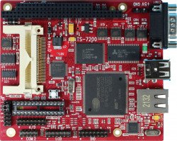
The TS-7200 is a compact, full-featured Single Board Computer (SBC) based upon the Cirrus EP9302 ARM9 CPU, which provides a standard set of on-board peripherals.
Getting Started
A Linux workstation is recommended and assumed for development using this documentation. For users in Windows or OSX, we recommend virtualizing Linux using VMWare or similar to make the full power of Linux available. The developer should be comfortable with Linux to work with embedded Linux on the target platform. Most of our platforms run Debian, which is recommended for ease of use if there is no personal distribution preference.
The main reasons that Linux is useful are:
- Linux filesystems on the microSD card can be accessed on the PC.
- More ARM cross-compilers are available.
- If recovery is needed, a bootable medium can be written.
- A network filesystem can be served.
- Builds such as Linux kernel, Buildroot, Yocto, and distro-seed will not work from WSL1/2 on a case-insensitive filesystem.
| WARNING: | Be sure to take appropriate Electrostatic Discharge (ESD) precautions. Disconnect the power source before moving, cabling, or performing setup procedures. Inappropriate handling may cause damage to the board. |
With the TS-7200 there is a terminal block power connector which is removable to expose 2 pins you can also use to supply power.
Get a Console
The default console is available on the DB9 port using the a 115200 baud, 8n1 connection with no flow control. You also must have JP2 in place in order to enable the console out. You can redirect console to COM2 by enabling JP4.
Use a null modem cable to connect the ARM system to your workstation. If you do not have a COM port on your system (as many newer systems do not), you can find a USB serial adapter that will bring out RS232.
Console from Linux
There are many serial clients for Linux, but 3 simple ones would be picocom, screen, and minicom. These examples assume that your COM device is /dev/ttyUSB0 (common for USB adapters), but replace them with the COM device on your workstation.
Linux has a few applications capable of connecting to the board over serial. You can use any of these clients that may be installed or available in your workstation's package manager:
Picocom is a very small and simple client.
picocom -b 115200 /dev/ttyUSB0
Screen is a terminal multiplexer which happens to have serial support.
screen /dev/ttyUSB0 115200
Or a very commonly used client is minicom which is quite powerful:
minicom -s
- Navigate to 'serial port setup'
- Type "a" and change location of serial device to '/dev/ttyUSB0' then hit "enter"
- If needed, modify the settings to match this and hit "esc" when done:
     E - Bps/Par/Bits          : 115200 8N1
     F - Hardware Flow Control : No
     G - Software Flow Control : No
- Navigate to 'Save setup as dfl', hit "enter", and then "esc"
Console from Windows
Putty is a small simple client available for download here. Open up Device Manager to determine your console port. See the putty configuration image for more details.


You can also telnet to the board with the default network configuration which will provide telnet.
Jumpers
| Jumper | Description | Address | Bit | Description |
|---|---|---|---|---|
| JP1 | Boot to serial port COM1. | N/A | ||
| JP2 | Enable serial console (COM1 Default) | 0x1080_000 | 0 | On=1 |
| JP3 | Write enable flash. | 0x1080_000 | 1 | On=1 |
| JP4 | Redirects console to COM2 (with JP2 on) | 0x1080_000 | 3 | On=0 |
| JP5 | Enables Testing | 0x1080_000 | 4 | On=0 |
| JP6 | User Configurable | 0x2280_000 | 0 | On=1 |
Backup / Restore
Onboard Flash
We currently do not support reflashing this onboard OS. As this is a fairly involved process, please submit an RMA and we can reflash it for you.
Compact Flash
If backing up on a separate workstation, keep in mind windows does not have direct block device support needed to write these images. You will also need to determine the CF card device. You can usually find this in the output of 'dmesg' after inserting the CF card and you will typically see something like '/dev/sdb' as the block device and '/dev/sdb1' for the first partition. On some newer kernels you will see '/dev/mmcblk0' as the block device and '/dev/mmcblkop1' for the first partition. For these examples I will use the '/dev/mmcblk0' format.
If you are backing up directly on the board you will likely need to use some kind of offboard storage like a thumbdrive or external hard drive.
Backup
Entire CF card
dd if=/dev/mmcblk0 of=/path/to/backup.dd bs=32k
Restore
Entire CF card
dd if=/path/to/backup.dd of=/dev/mmcblk0 bs=32k
eCos RedBoot
RedBoot is a feature rich boot-ROM monitor, that allows manipulation of the on-board flash, JFFS and YAFFS images, loading and execution of a kernel or executable from either tftp (trivial ftp), http or flash, and gdb debugging stubs. From RedBoot, one can load and execute any standalone binary. Most commonly, a Linux kernel binary is used. One can also write applications within the eCos environment and load them with RedBoot. Please refer to Sourceware for more information on programming for eCos.
By default, a pre-existing RedBoot script is executed on initialization time, if not interrupted by the user within one second. The default script instructs RedBoot to load the Linux kernel from the flash, and instructs the Linux kernel to use the JFFS/YAFFS image on the flash chip for its root file system. One can view the RedBoot defaults for the board, as well as the default script, by entering “fconfig -l” at the RedBoot command prompt (Ctrl+C within one second after power up).
The defaults can be changed by simply entering “fconfig” at the RedBoot prompt and answering the prompts. A final chance to write or discard the changes to the board will be given by RedBoot. Also, the main RedBoot commands can be viewed by entering “help” at the prompt, and further information about a single command can be viewed by typing “help <command name>”.
Loading and Executing a Kernel
RedBoot can load a kernel or executable via the serial console, a tftp server, http server, or directly from flash. The Linux kernel must be loaded into memory address 0x00218000.
Flash
Loading the kernel from flash is done automatically by RedBoot in the default script with the following command:
fis load vmlinux
HTTP
Prior to loading a new kernel into RebBoot using HTTP, make sure you have configured RedBoot with a network configuration that can reach the network. You may use the RedBoot "fconfig" command to set network parameters. Get to the RedBoot prompt by hitting Ctrl+C key immediately after power on and type the following command:
load -v -r -b 0x00218000 -m http -h <http sever IP> <kernel name>
For example:
load -v -r -b 0x00218000 -m http -h 67.40.67.44 /ftp/ts7kv/vmlinuxts7200ts9.bin
TFTP
To load a kernel from a simple TFTP server, the following command is needed:
load -r -b 0x00218000 -h <tftp server IP> <kernel name>
For example:
load –b 0x00218000 –h 192.168.0.1 vmlinux
Executing a loaded kernel
Now that a kernel has been loaded into memory, it can be executed. This is accomplished with the following command:
exec -c "<kernel parameters>"
For example:
exec -c "console=ttyAM0,115200 ip=dhcp root=/dev/mtdblock1"
The “exec” command executes the loaded kernel image, passing to the kernel the arguments specified via the “-c” switch. In the previous example, kernel messages are sent out on the first serial port (note that ttyAM0 is used instead of the familiar ttyS0) at 115200 baud and the root file-system is on the first mtdblock of the flash chip.
On the TS-7200 model, to load the root file system from the Compact Flash card, the following command should be used instead:
exec -c "console=ttyAM0,115200 ip=dhcp root=/dev/hda1"
To load from an NFS root:
exec -c "console=ttyAM0,115200 ip=dhcp nfsroot=<IP of NFS server>:</path/to/NFSROOT>"
Operating Systems
On the compact flash we have enough room to provide Debian. This provides a very mature OS with many packages, but does require significantly more space. For the onboard flash we have developed TS-Linux which requires very little space while still providing a powerful system. We have also created a NetBSD port for this board.
Linux
The two linux distributions we support includes our own TS-Linux, and Debian. Both of these will use the same kernel.
Debian
Our boards boot a standard Debian installation which provides a large amount of software that you can install with relatively little effort. See the Debian page for more general information on installing/removing software, and further documentation.
For this series we provide the Debian versions Woody, Sarge, Etch and Lenny. The EP9302 supports both OABI and EABI, so future Debian distributions may be run on the SBC, but will not be supported. We do provide distributions available as archives separate from the images. You can find them on this folder on the ftp. You will need a linux system to extract it:
# Replace the /dev/sdb device with your card
# on your workstation
mount /dev/sdb3 /mnt/sd/
cd /mnt/sd/
tar --numeric-owner -xvf /path/to/distribution.tar.gz
cd ../
umount /mnt/sd/
TS-Linux
This is our minimalistic Linux system based off of busybox which provides a very simple OS to run your application.
Network Configuration
The main utilities for network configuration under Linux are:
- ifconfig: prints network settings and configures ethernet interfaces
- ifup: turns given network interface up
- ifdown: turns given network interface down
Entering “ifconfig” shows the current ethernet settings. These utilities require a network device as parameter. On Linux, the ethernet devices are generally named eth0, eth1, etc. Therefore, the command “ifup eth0” or “ifconfig eth0 up” brings up the on-board ethernet interface on TS-72XX SBCs.
To configure the network, you need to manage the proper configuration files. On TS-Linux systems, these files are located in the “/etc/sysconfig/” directory. By default, Linux systems on TS-72XX boards are configured to assign the IP 192.168.0.50 to the on-board ethernet interface.
To configure the network when booting to the TS-Linux image on the flash chip, the files in "/etc/sysconfig/" must be edited. Network interfaces are configured on a file per interface basis. The first Ethernet device, eth0, is controlled by the file /etc/sysconfig/ifcfg-eth0". An example of "ifcfg-eth0" is shown below:
 DEVICE=eth0 #Name of ethernet interface
 IPADDR=192.168.0.50 #IP address of this ethernet interface
 NETMASK=255.255.255.0 #Used with NETWORK to determine local IPs
 NETWORK=192.168.0.0 #Used with NETMASK to determine local IPs
 BROADCAST=192.168.0.255 #Broadcast IP for system wide messages
 BOOTPROTO=static #Static IP (change "static" to “DHCP”)
 ENABLE=yes #Load device on boot
The TCP/IP network settings are configured in the file '/etc/sysconfig/network_cfg':
 NETWORKING=yes #Enable networking on startup
 GATEWAY="192.168.0.1" #Gateway for internet access
 GW_DEV=eth0 #Default gateway
 HOSTNAME=ts7200 #Host name of this computer
 BOOTPROTO=no
 FORWARD_IPV4=no
 DEFRAG_IPV4=no
The TCP/IP name resolution server is configured in '/etc/resolv.conf':
nameserver 192.168.0.1 #Name server for domain name lookups
Those lines starting with a # symbol are comments. As the above example shows, eth0 is given the static address of 192.168.0.50. If one wishes eth0 to obtain its IP from a DHCP server, then change the line BOOTPROTO=static to BOOTPROTO=dhcp. In order to test the default network settings with TS-Linux, open a web browser and use the embedded Apache web server by entering the default IP 192.168.0.50, or simple "ping" or "telnet" to 192.168.0.50.
Services
TS-Linux includes solutions for the main network services, including Telnet, HTTP, FTP, SSH, NFS and Mail. Some of these services can be started, restarted or stopped by management scripts located at the "/etc/init.d" directory. For example, the following command will restart the apache server:
/etc/init.d/apache restart
Also, the "/etc/inet.conf" file is used to configure the initialization and parameters of other services.
Software Development
Most of our examples are going to be in C, but Debian will include support for many more programming languages. Including (but not limited to) C++, PERL, PHP, SH, Java, BASIC, TCL, and Python. Most of the functionality from our software examples can be done from using system calls to run our userspace utilities. For higher performance, you will need to either use C/C++ or find functionally equivalent ways to perform the same actions as our examples.
The most common method of development is directly on the SBC. Since debian has space available on the CF card, we include the build-essentials package which comes with everything you need to do C/C++ development on the board. For TS-Linux you will have to cross compile off the board.
Editors
Vim is a very common editor to use in Linux. While it isn't the most intuitive at a first glance, you can run 'vimtutor' to get a ~30 minute instruction on how to use this editor. Once you get past the initial learning curve it can make you very productive. You can find the vim documentation here.
Emacs is another very common editor. Similar to vim, it is difficult to learn but rewarding in productivity. You can find documentation on emacs here.
Nano while not as commonly used for development is the easiest. It doesn't have as many features to assist in code development, but is much simpler to begin using right away. If you've used 'edit' on Windows/DOS, this will be very familiar. You can find nano documentation here.
Compilers
We only recommend the gnu compiler collection. There are many other commercial compilers which can also be used, but will not be supported by us. You can install gcc on most boards in Debian by simply running 'apt-get update && apt-get install build-essential'. This will include everything needed for standard development in c/c++.
You can find the gcc documentation here. You can find a simple hello world tutorial for c++ with gcc here.
Build tools
When developing your application typing out the compiler commands with all of your arguments would take forever. The most common way to handle these build systems is using a make file. This lets you define your project sources, libraries, linking, and desired targets. You can read more about makefiles here.
If you are building an application intended to be more portable than on this one system, you can also look into the automake tools which are intended to help make that easier. You can find an introduction to the autotools here.
Cmake is another alternative which generates a makefile. This is generally simpler than using automake, but is not as mature as the automake tools. You can find a tutorial here.
Debuggers
Linux has a few tools which are very helpful for debugging code. The first of which is gdb (part of the gnu compiler collection). This lets you run your code with breakpoints, get backgraces, step forward or backward, and pick apart memory while your application executes. You can find documentation on gdb here.
Strace will allow you to watch how your application interacts with the running kernel which can be useful for diagnostics. You can find the manual page here.
Ltrace will do the same thing with any generic library. You can find the manual page here.
Cross Compiling
We have prepared a version of Eclipse to work with the board which is available here. There are instructions provided with the archive, and Eclipse has many tutorials for working with it available.
For development from a Linux workstation you will want to use the toolchain here. Extract it to the root of your filesystem, and run that version of gcc to prepare the ARM binary.
To Compile:
[user@localhost]$ /usr/local/arm-oabi-toolchain/arm-unknown-linux-gnu/bin/arm-unknown-linux-gnu-gcc hello.c -o hello
[user@localhost]$ file hello
hello: ELF 32-bit LSB executable, ARM, version 1, dynamically linked (uses shared libs), for GNU/Linux 2.6.26, not stripped
There are many ways to transfer the compiled binaries to the board. Using a network filesystem such as sshfs or NFS will be the simplest to use if you are frequently updating data, but will require more setup. See your linux distribution's manual for more details.
The simplest method to set up is using ssh/sftp from Debian. You can use winscp if from windows, or scp from linux. Make sure you set a password from debian for root. Otherwise the ssh server will deny connections. From winscp, enter the ip address of the SBC, the root username, and the password you have set. This will provide you with an explorer window you can drag files into. For TS-Linux, you can set up an NFS share or transfer files using a USB drive.
For scp in linux, run:
#replace with your app name and your SBC IP address
scp hello root@192.168.0.50:/root/
After transferring the file to the board, execute it:
ts7200:~# ./hello
Hello world!
Kernel Compile Guide
Linux 2.4.26
| WARNING: | BACKUP YOUR DATA FIRST |
Prerequisites
RHEL/Fedora/CentOS:
yum install ncurses-devel ncurses
yum groupinstall "Development Tools" "Development Libraries"
Ubuntu/Debian:
apt-get install build-essential libncurses5-dev libncursesw5-dev
For other distributions, please refer to their documentation to find equivalent tools.
Set up the Sources and Toolchain
wget ftp://ftp.embeddedTS.com/ts-arm-sbc/ts-7200-linux/cross-toolchains/crosstool-linux-gcc-3.3.4-glibc-2.3.2-0.28rc39.tar.bz2

bunzip2 crosstool-linux-gcc-3.3.4-glibc-2.3.2-0.28rc39.tar.bz2

tar -xvf crosstool-linux-gcc-3.3.4-glibc-2.3.2-0.28rc39.tar

wget ftp://ftp.embeddedTS.com/ts-arm-sbc/ts-7200-linux/sources/tskernel-2.4.26-ts11-feb232011.tar.gz

tar -xvzf tskernel-2.4.26-ts11-feb232011.tar.gz

cd linux24
Open the Makefile and edit CROSS_COMPILE to say:
CROSS_COMPILE = insert/your/directory/structure/here/crosstool/arm-linux/gcc-3.3.4-glibc-2.3.2/bin/arm-linux-
Next the config file needs to be set up. Run "make menuconfig"
- Load the TS-7200 config file by typing "L" three times, "ENTER", and specify "arch/arm/def-configs/ts7200". When finished, save and exit back to the menuconfig
- Exit menuconfig and be sure to say "Yes" to save any changes
make dep
make Image
make zImage
The kernel will be present at "arch/arm/boot/Image" or "arch/arm/boot/zImage" for the compressed version.
| Note: | Large kernels may not fit in the kernel partition of the boot device. Check the size of the newly created kernel and ensure it will fit before writing to disk. |
The modules can then be installed to a local directory and packed in to an archive to unpack on the SBC:
make modules
INSTALL_MOD_PATH="`pwd`/newmodules" make modules_install
tar czvf modules_2.4.26-ts11.tar.gz -C newmodules/ .
Copy the modules tarball archive to a USB drive or other accessible media (FTP, NFS, etc.), then unpack the archive to the root folder of the device. See the redboot instructions for loading a kernel permanently on devices that use RedBoot.
| Note: | Once installed to the target filesystem, "depmod" should be invoked manually to update the module loading and dependency list. |
NetBSD
NetBSD is a very powerful open operating system which runs on everything including your toaster.
Initial NetBSD support for the TS-7200 was committed to the NetBSD -current CVS repository on December 24, 2004 as a subconfiguration of the NetBSD/evbarm port. Current supported peripherals are described on the NetBSD/evbarm webpage. As a kernel, the most notable hardware support difference between the current NetBSD kernel and the Linux 2.4.26 kernel currently shipping by default with the TS-7200 is that NetBSD has an isabus driver that allows PC/104 cards to be more fully utilized on the TS-7200. Getting generic ISA bus drivers to work with Linux can be very difficult due to the x86 style ISA assumptions throughout the kernel. Linux right now does have something NetBSD does not and that is support for using the onboard flash as a filesystem (NetBSD requires the CF to boot). NetBSD has support for the watchdog timer on the TS-7200 and can also boot very easily to a USB thumb drive or mass storage device. Linux currently has no watchdog driver and has to use a very technical incantation involving an initrd and a pivot_root to boot USB drives. Kernel bootup time is slightly longer on NetBSD than Linux, but can be improved by disabling certain drivers and certain (overly conservative) delays.
Installing NetBSD
All TS-7200's come pre-installed with Linux since Linux is Technologic System's most marketable platform. Installing NetBSD is not difficult and can be done from the RedBoot ROM monitor completely from the internet. Before you start, you'll want to make sure you have at least version 1.04 of the TS-BOOTROM firmware installed. Also, there is currently no gzimg for the 16MB onboard flash versions of the TS-7200. Send a message to joff-AT-embeddedTS.com if you have a 16MB flash unit you would like to try NetBSD on. The first thing you'll want to do is use the RedBoot command fconfig to set your IP address and default gateway so that you can access the internet. After that, you need to load the 5MB install kernel from the internet using the command:
load -v -r -b 0x00200000 -h 67.40.67.44 -m http /ftp/ts-arm-sbc/ts-7200-netbsd/netbsd-TS7200_INSTALL.bin
Note that this may take some time as eCos/RedBoot is not particularly speedy at downloading via HTTP. You may alternatively download the file to a TFTP or HTTP server on your local network which may speed things up. After successfully downloading the install image to RAM, type go to start the kernel and menu driven installation program. The NetBSD installation program will take you through installing NetBSD to your CompactFlash card or USB thumb drive. Just installing the minimal number of sets will require a 128MB CF, and although you can run the full OS with compilers in a 256MB CF, you need 512MB to install it because of required temporary storage of the downloaded set tarballs. When the time comes to ask for the installation medium, choose "FTP" and accept the default parameters since the installation kernel you downloaded from Technologic Systems will default to the correct FTP location (also at Technologic Systems).
After the OS has been installed to the CF, you need to write a kernel to the onboard flash and tell RedBoot to boot it. A kernel that boots to CF is downloadable via HTTP and can be written using the following sequence of commands:
- Load NetBSD gzimg from HTTP into RAM
load -v -r -b 0x00200000 -h 67.40.67.44 -m http /ftp/ts-arm-sbc/ts-7200-netbsd/gzimg_TS7200_wd0_flash_0x60660000
- To delete flashed Linux kernel
fis delete vmlinux
- Puts the gzimg into the RedBoot FIS
fis create -b 0x00200000 -l 0x160000 -f 0x60660000 netbsd.gz
Once the gzimg image has been written to flash, you can modify your RedBoot bootscript to issue the command go 0x60660000 which will then start NetBSD on your TS-7200
Using NetBSD
NetBSD has a separate sub-project dubbed pkgsrc that handles package management and building of the several thousand other open-source projects. This is somewhat akin to RedHat's RPM or Debian's dpkg/apt-get facilities. Package dependencies are downloaded and installed automatically providing functionality similar to Debian's apt-get. Note, however, the typical usage of the NetBSD pkgsrc framework is downloading/extracting the pkgsrc framework tarball into /usr/pkgsrc and building each package right on the hardware that will run it. This is a little bit more involved on the TS-7200 since one rarely has the patience to compile completely on a 200Mhz ARM. Instead, the recommended way would be to use the distcc compiler to distribute the compiling to a higher power workstation running the distccd daemon with the ARM netbsd cross toolchain across the network. This way, the TS-7200 is still running the build, but the bulk of the CPU-intensive parts are offloaded to another machine.
Besides pkgsrc, another notable difference is in the NetBSD startup configuration. Linux distributions vary, but they typically use the SysV initialization scheme with numbered runlevels 1-6, startup scripts in /etc/init.d/* and specially named symlinks in /etc/init.d/rc##.d directories corresponding to each runlevel. NetBSD uses a simplified startup configuration where single lines of the form sendmail=YES or inetd=NO are appended to the /etc/rc.conf file. System defaults are sourced first from /etc/defaults/rc.conf and the user may open this file for finding all the available modifiable configuration knobs and then override them with entries in /etc/rc.conf.
Network interfaces are also slightly different in NetBSD. Instead of each ethernet like device being named eth0, eth1, eth2, etc., each device is named according to the actual device. On the TS-7200, the on-board ethernet is named "epe0", short for EP93xx Ethernet. To set IP addresses, the ifconfig command is available with semantics similar to those in Linux. Alternatively, you may have the system set the device up at bootup by appending a line of the form ifconfig_epe0="192.168.0.50" to the /etc/rc.conf file. To use DHCP, append a line dhclient=YES to /etc/rc.conf. The default route is set with a line in /etc/rc.conf of the form defaultroute="192.168.0.1".
CPU Functionality

The EP9302 features an advanced 200 MHz ARM920T processor design with a memorymanagement unit (MMU) that allows support for high-level operating systems such as Linux, Windows CE, and other embedded operating systems. The ARM core operates from a 1.8 V supply, while the I/O operates at 3.3 V with power usage between 100 mW and 750 mW (dependent on speed). As a general-purpose processor, it provides a standard set of peripherals on board and a full set of Technologic Systems add-on peripherals via the standard PC/104 Bus.
The ARM920T's 32-bit architecture, with a five-stage pipeline, consisting of fetch, decode, execute, memory, and write stages, delivers very impressive performance at very low power. The EP9302 CPU has a 16 KB instruction cache and a 16 KB data cache to provide zero-cycle latency to the current program and data, or they can be locked to guarantee no-latency access to critical sections of instructions and data. For applications with instruction-memory size restrictions, the ARM920T’s compressed Thumb instruction set can be used to provide higher code density and lower Flash storage requirements.
Setting the CPU Clock Speed
There are two methods that can be used for this. The simplest by far is to use the ts7000.subr script located in /initrd. This script will add the following commands for setting CPU speed:
cpu_speed_max
cpu_speed_166
cpu_speed_42
cpu_speed_min
The other method is more complicated and involves poking values into the configuration registers. For further information on which registers, consult the source code in the ts7000.subr script. The registers themselves are currently undocumented. It is recommended to use only the values demonstrated by the script above.
Interrupts
The EP9302 interrupt controller allows up to 54 interrupts to generate an Interrupt Request (IRQ) or Fast Interrupt Request (FIQ) signal to the processor core. Thirty-two hardware priority assignments are provided for assisting IRQ vectoring, and two levels are provided for FIQ vectoring. This allows time critical interrupts to be processed in the shortest time possible.
The EP9302 interrupt controller also includes the following features:
- Supports 54 interrupts from a variety of sources (such as UARTs, GPIO and ADC)
- Routes interrupt sources to either the ARM920T’s IRQ or FIQ (Fast IRQ) inputs
- Three dedicated off-chip interrupt lines operate as active high level sensitive interrupts
- Any of the 19 GPIO lines maybe configured to generate interrupts
- Software supported priority mask for all FIQs and IRQs
| Note: | For peripheral driver development purpose, notice that the external IRQ lines 5,6 and 7, which are ISA/X86 architecture based, are mapped to EP9302 external interrupt lines 22, 33 and 40, respectively. For further information about interrupts, including the EP9302 interrupt controller and map, refer to the EP9302 User's Guide, chapter 5. |
Memory
TS-7200 uses three type of memory. The SDRAM is the fast access volatile memory used to run applications by the processor and the on-board flash is the non-volatile memory used for storage purpose. Flash memory may also be added using USB memory drivers. On-Board SDRAM The TS-7200 uses 32 MB SDRAM technology to provide 32 or 64 MB of high-speed volatile memory. The memory is soldered directly to the board, making the TS-7200 more reliable in high-vibration environments.
The TS-7200's RAM is not contiguous in the physical memory map of the EP9302. But the MMU is programmed to remap the blocks of RAM to appear as a contiguous block of memory at the very beginning of the virtual memory map. In the case of a 256 Megabit SDRAM chip (32 MB), it is located at 0 through 32 MB in the virtual memory map.
ADC
The Cirrus EP9302 features a 5 channel, 12-bit Analog to Digital Converter with an analog multiplexer, having an input range of 0 to 3.3 V. The Cirrus A/D converter can do a maximum of 925 samples per second, and requires a settling time of 2 milliseconds between channel switches. The DIO Port pins 4 and 6 are connected to two of the EP9302 12-bit A/D converter inputs (ADC0 and ADC4, respectively). The A/D lines on the DIO1 header can be used to measure analog signals in the range of 0 to 3.3V.
To maintain 12-bit accuracy, the analog signal being measured must have a low source impedance (less than 10 ohms). Otherwise, an operational amplifier may need to be added to buffer the A/D input. For detailed information, please see the Cirrus EP9301 User's Guide, page 518.
The following steps outline the software execution to use the Cirrus A/D converter:
- Unlock the software lock before setting the TSEN bit in the ADCClk register by writing 0xAA to the ADCSWLock register (0x8090_00C0). “OR” in the TSEN bit (bit 31) to the ADCClkDiv register (0x8093_0090)
- Unlock the software lock (again) before OR'ing in the ADCEN (ADC clock enable, bit 31) to 0x8093_0080
- Clear bit 2, the ADCPD (ADC Power Down) bit, at 0x8093_0080. This bit MUST be set to 0 (see page 91 of the EP9301 User's Guide)
- After unlocking the software lock, write the channel's magic value (see Cirrus EP9301 User's Guide, table 20-2) to the ADCSwitch register (0x8090_0018) to select that channel for the next data acquisition
- Poll the ADCResult register (0x8090_0008) until bit 31 is not set
- Using a 32 bit read operation, read the result from 0x8090_0008, masking off the upper 16 bits
Interpreting Cirrus A/D Converter
The Cirrus on-chip A/D converter is a successive approximation A/D converter. Each A/D channel is calibrated on the EP9302 and these 16-bit values are stored in non-volatile EEPROM. These calibration values minimize the offset errors and gain errors in the EP9302 A/D. It is important for the user program to use these values as per our sample code, which can be found either on our website or in the CD included in the Developer's Kit. Two reference points, 0 and 2.5 Volts, with the corresponding reference values stored in EEPROM. Bytes 0x07EB through 0x07FE of the EEPROM hold a two dimensional array:
[channel number][0V ref. point, 2.5V ref. Point]
The reference points are stored as a 16 bit value, and should be used to correlate the values returned by the Cirrus A/D converter to voltage.
We have an example of using the EP9302 ADC here.
DIO
There are 20 Digital Input/Output (DIO) lines available on the TS-7200 . These are available on two headers labeled “DIO” and “LCD”. The header labeled LCD can be used as 11 DIO lines or as an alphanumeric LCD interface. The header labeled DIO has 9 DIO pins available. In addition to the DIO signals, each header also has a power pin and Ground available. The LCD header has 5V power available while the DIO header has 3.3V power.
Three pins on the DIO header are used to bring out the EP9302 SPI bus. By using some of the DIO pins as peripheral Chip Select signals, a complete interface is available for SPI peripherals. It is also possible to bring out a fourth SPI bus function [SPI_Frame] by adding a 10 ohm resistor in the position labeled R1 on TS-7200 boards. This signal is not required for many SPI peripherals but it may prove useful in some applications.
All of the DIO lines are programmable as either inputs or outputs and the direction of each I/O pin can be individually programmed. All DIO control registers are 8-bits wide and aligned on word (32-bit) boundaries. For all registers, the upper 24 bits are not modified when written and are always read back as zeros. Every DIO pin has two registers used to access it, an 8-bit data register and an 8-bit data direction register (DDR). The DDR controls whether each DIO pin is an input or an output (”1” = output). Writing to the data register only affects pins that are configured as outputs. Reading the data register always returns the state of the DIO pin.
Onboard Flash
The TS-7200 uses an Intel 3.3V Strata Flash chip for its on-board Flash resource. For the standard 8 Megabyte chip, this is composed of 64 uniform sectors with 128 Kbytes per sector. The first sector is reserved for the TS-BOOTROM code. The TS-BOOTROM code initializes various internal configuration registers for proper operation for the TS-7200 design and initializes and tests the SDRAM. The next 48 sectors (6 Mb) are used for the JFFS2 file system. This is a journaling file system that uses wear leveling at the file system level to maximize Flash lifetime. It is also extremely tolerant of power failures during file write sequences. The last 1920Kb are reserved for the RedBoot ROM monitor, RedBoot FIS (Flash Image System) and RedBoot FCONFIG (Flash config). The default Linux kernel, vmlinux, is pre-loaded in the FIS and the default boot script and Ethernet MAC address are contained in the FCONFIG. You may also use the RedBoot FIS to store and load Flash images that contain eCos applications or other OS/RTOS bootloaders.
The physical address of the Flash chip is 0x6000_0000 through 0x607F_FFFF for the 8 MB chip. It is possible to use larger sizes of the Intel Strata Flash than the standard 8MB chip. The TS-7200 is designed to accommodate both 16 MB and 32 MB chips. Please call Technologic Systems to discuss lead times and current costs for these options. The entire Flash chip can be write-protected by removing Jumper #3. When JP3 is not installed the Flash chip becomes a read-only resource. The designer should be aware that Flash technology does have a wear-out mechanism that should be considered in all designs. The Intel Strata Flash memory is guaranteed capable of a minimum of 100,000 write/erase cycles. This means that if you completely erase and rewrite the entire Flash drive 10 times a day, it would take over 27 years before any problems would occur. Reading the Flash produces no wear at all.
COM Ports
The TS-7200 have two asynchronous serial ports (COM1 and COM2) which provide a means to communicate with external serial devices. Each is independently configured as a 16C550- type COM port that is functionally similar to a standard PC COM port. These ports have 16-byte FIFOs in both the receive and the transmit UART channels. Both COM ports can support all standard baud rates up through 230.4Kbaud. Both COM ports may be configured to use a DMA channel (useful when very high baud rates are being used). COM1 and COM2 UARTs can generate:
- Four individually maskable interrupts from the receive, transmit, and modem status logic blocks
- A single, combined interrupt that is asserted if any of the individual interrupts are asserted and unmasked
The COM1 port can also support the HDLC protocol. Refer to the Cirrus EP9302 User's Guide for more details. The COM2 port can optionally support RS-485 half or full duplex levels.
The TS-Kernel includes a patch to toggle the automatic TX Enable on RS485. This is used by setting TIOC_SBCS485 to automatically toggle transmit enable, or clearing TIOC_SBCS485 for manual operation.
Temperature Sensor (OP-TMPSENSE)
The onboard temperature sensor option is populated on the back side of the TS-7200 PCB. It is attached to pin DIO_17. Sample code for accessing the data from this chip is located here.
Compact Flash / USB Flash
Additional non-volatile storage may be added with a USB flash drive or a Compact Flash card. These devices supply additional non-volatile storage either for data or for a complete operation system distribution. The developer's kit includes a USB flash thumb-drive or Compact Flash card pre-loaded with Debian.
Flash memory provided by these devices behaves much as a hard drive does with sizes ranging from 32MB to 1GB. These products are inherently more rugged than a hard drive since they are completely solid-state with no moving parts. However, they have the added advantage of being removable media.
Drivers are available in the TS-Linux distribution to support USB flash drives. One can load Debian OS with two scripts provided by the on-board flash TS-Linux file system. First, invoke /usr/bin/loadUSBModules.sh, then run the script /usr/bin/loadUSB.sh to chroot into the Debian OS.
The on-board Compact Flash connector/socket enables Compact Flash cards to be plugged to the TS-7200 SBC. Compact Flash cards have the added advantage of being removable media. A SanDisk USB Compact Flash reader/writer (which is included in the TS-7200 Development Kit) is recommended for the host PC for file transfers. This results in the ability to quickly move files from a host PC to the TS-7200 using a Compact Flash card as the removable media. While a USB Compact Flash reader allows for hot swapping of the Compact Flash card on the host PC, the Compact Flash interface on the TS-7200 is not hot swappable. The TS-7200 must be rebooted after removing or installing a Compact Flash card.
The format of the CF card must be in EXT2 format for proper operation with Linux as a root file system.
| WARNING: | The TS-7200 always needs to be powered-off before swapping CF cards. |
Ethernet
The EP9302 Ethernet LAN controller incorporates all the logic needed to interface directly to any MII compatible Ethernet PHY chip. A low-power Micrel KS8721 chip is used to implement the Ethernet PHY function and an integrated RJ-45 connector with built-in 10/100 transformer and LED indicators completes the Ethernet sub-system.
This board has both a LINK/ACTIVITY LED and a 10/100 speed LED built into each RJ-45 connector that indicates the current Ethernet status. The LINK LED (left side of connector, green) is active when a valid Ethernet link is detected. This LED should be ON whenever the board is powered and properly connected to a 10/100BaseT Ethernet network. The LINK/ACTIVITY LED will blink to indicate network activity for either inbound or outbound data. The SPEED LED (right side of connector, amber) will be on when a 100Mb network is detected and off for a 10Mb network. Both of these LEDs are controlled by the KS8721 and do not require any overhead by the processor.
The Ethernet PHY chip can be powered down, under software control, to save approximately 90 mA of current consumption. This is controlled by the EP9302 Digital output on Port H, bit 2. A logic zero will power down the KS8721 PHY interface.
USB Host
The USB Connector on the TS-7200 provide two USB interfaces for the user. These are directly connected to the EP9302 processor, which integrates an USB dual-port Open Host Controller Interface (Open HCI), providing full-speed serial communications ports at a baud rate of 12 Mbits/sec. Up to 127 USB devices (printer, mouse, camera, keyboard, etc.) and USB hubs can be connected to the USB host in the USB “tiered-star” topology.
This includes the following features:
- USB 2.0 compatible
- Open HCI Rev 1.0 compliant
- USB device connections support at both low-speed (1.5 Mbps) and full-speed (12 Mbps)
- Root HUB integrated with 2 downstream USB ports
- Transceiver buffers integrated, over-current protection on ports
- Supports power management
- Operates as a master on the bus
CPLD Functionality
The inclusion of a Xilinx 9572 CPLD on the SBC allows customized programming for customers with special needs, without having to do a more expensive board redesign. The CPLD is responsible for taking control over the internal components communication through glue logic implementation. For instance, the CPLD is used to control the NAND flash through internal registers configuration.
The CPLD handles control signals on the PC104 bus, has a watchdog timer, enables jumper settings reading, handles the reset button, interfaces to the real-time clock and controls the EEPROM chip select. It also implements peripheral features that, together with EP9302 modules, makes available an advanced set of communication ports, DIO pins, ADC converters, and others.
Watchdog Timer
The WDT can be used to prevent a system “hanging” due to a software failure. The WDT causes a full system reset when the WDT times out, allowing a guaranteed recovery time from a software error. To prevent a WDT timeout, the application must periodically “feed” the WDT by writing a specific value to a specific memory location.
Watchdog Control Registers
| Register | Access | Address |
|---|---|---|
| Control Register | Read / Write | 0x2380_0000 |
| Feed Register | Write Only | 0x23C0_0000 |
The WDT Control register must be initialized with the timeout period desired. This may be as short as 250 mS or may be as long as 8 seconds. After the WDT has been enabled, the WDT counter begins. The application software can reset this counter at any time by “feeding” the WDT. If the WDT counter reaches the timeout period, then a full system reset occurs.
| Value | Function |
|---|---|
| 0x00 | Watchdog Disabled |
| 0x01 | 250ms |
| 0x02 | 500ms |
| 0x03 | 1s |
| 0x04 | Reserved |
| 0x05 | 2s |
| 0x06 | 4s |
| 0x07 | 8s |
In order to load the WDT Control register, the WDT must first be “fed”, and then within 30 uS, the WDT control register must be written. Writes to this register without first doing a “WDT feed”, have no affect. In order to clear the WDT counter (feeding the watchdog), a value of Hex 05 must be written to the WDT Feed register. By default, a user process does not have the physical address space (access) of the watchdog registers mapped. When using the Linux OS, the watchdog can be reached from user C code by using the mmap() system call on the /dev/mem special file to map the areas of physical address space into process user address space.
| WARNING: | Use only the Watchdog Timer implemented by Technologic Systems in the CPLD. The Watchdog Timer included in the EP9302 has serious problems. |
This example shows feeding the watchdog timer 8s at a time.
#include<unistd.h>
#include<sys/types.h>
#include<sys/mman.h>
#include<stdio.h>
#include<fcntl.h>
#include<assert.h>

int main(void)
{
	volatile unsigned char *wdt_control;
	volatile unsigned char *wdt_feed;

	int fd = open("/dev/mem", O_RDWR|O_SYNC);
	assert(fd != -1);

	wdt_control = (unsigned char *)mmap(0,getpagesize(),PROT_READ|PROT_WRITE,MAP_SHARED,fd,0x23800000);
	wdt_feed = (unsigned char *)mmap(0,getpagesize(),PROT_READ|PROT_WRITE,MAP_SHARED,fd,0x23C00000);

	*wdt_feed=0x05;
	*wdt_control=0x07;

	while(1)
	{
		*wdt_feed=0x05;
		sleep(5);
	}
}
MAX197 ADC (OP-ADC)
The TS-7200 supports an optional eight-channel, 12-bit A/D converter (ADC) with a conversion time of 12 uS. This will allow up to 60,000 samples per second. Each channel is independently software programmable for a variety of analog input ranges: -10V to +10V, -5V to +5V, 0V to +10V, or 0V to +5V. This allows an effective dynamic range of 14 bits.
The datasheet for the MAX197 is available here.
| I/O Address | Access | Description |
|---|---|---|
| 0x10F0_0000 | Write Only | Initiate A/D Conversion |
| 0x10F0_0000 | Read Only | LSB of Conversion |
| 0x10F0_0001 | Read Only | MSB of Conversion |
| 0x2240_0000 | Read Only | Bit 0 = 1 if OP-ADC is installed |
| 0x1080_0000 | Read Only | Bit 7 = 0 when conversion completed. |
Each channel is overvoltage tolerant from -16V to + 16V, and a fault condition on any channel will not affect the conversion result of the selected channel. This is all accomplished with a 5V only power supply; no negative supply voltage is required. The Maxim MAX197 chip can be replaced with a MAX199 chip if a lower range of analog input levels is required (-4V to +4V, -2V to +2V, 0V to 4V, and 0V to 2V).
A/D Convrol Register 0x10f0_0000 (Write Only)
| Bit | Description | Details |
|---|---|---|
| 0-2 | Analog Channel Select | Channels 0-7 |
| 3 | Unipolar / Bipolar | 0 = Unipolar (0-5V)
1 = Bipolar (-5v to +5v) |
| 4 | Range Select | 0 = 5V range
1 = 10V range |
| 5-7 | Mode Bits | 0, 1, 0 |
This example program assumes a test fixture is attached to the A/D header with 2.35 VDC on all even channels and 1.18 VDC on all odd channels. This test uses a 0-10V unipolar. Therefore even channels are nominally 22% (21.5-22.5 => good) and odd channels are nominally 11% (10.5-11.5 => good).
#include<unistd.h>
#include<sys/types.h>
#include<sys/mman.h>
#include<stdio.h>
#include<fcntl.h>
#include<assert.h>
#include<time.h>
#include<stdlib.h>

#define PLD_ATOD_SET     0x01		//bit0 at OPTIONS
#define OPTIONS          0x22400000
#define CTRL_BYTE        0x10f00000
#define BUSY             0x10800000
#define CHANNEL_0        0x50
#define CHANNEL_7        0x57
#define BUSYBIT          0x80

int main(int argc, char **argv)
{
	volatile unsigned char *options, *controlByte, *busy;
	unsigned char *registerValue;
	unsigned short *results;
	double percentage;
	int ctrlByte, n;
	int fd = open("/dev/mem", O_RDWR|O_SYNC);
	assert(fd != -1);

	setvbuf(stdout, NULL, _IONBF, 0);

	/* Lets intialize our pointers */
	options = mmap(0, getpagesize(), PROT_READ|PROT_WRITE, MAP_SHARED, fd,
	  OPTIONS);
	assert(options != MAP_FAILED);
	controlByte = mmap(0, getpagesize(), PROT_READ|PROT_WRITE, MAP_SHARED,
	  fd, CTRL_BYTE);
	assert(controlByte != MAP_FAILED);
	busy = mmap(0, getpagesize(), PROT_READ|PROT_WRITE, MAP_SHARED, fd,
	  BUSY);
	assert(busy != MAP_FAILED);

	printf("checking if MAX197-ADC option is set...");
	registerValue = (unsigned char *)options;
	if( *registerValue & PLD_ATOD_SET ) {
		printf("ok\n");
	} else {
		printf("FAIL, not set\n");
		return 1;
	}

	/* Lets go do the conversions */
	for( ctrlByte = CHANNEL_0; ctrlByte <= CHANNEL_7; ctrlByte++)
	{
		//lets write out our control byte
		*controlByte = ctrlByte;

		printf("waiting for ADC to respond on channel %d...",
		  ctrlByte - CHANNEL_0);
		//lets poll the busy bit to determine when the conversion is done
		registerValue = (unsigned char *)busy;

		n = 0;
		while(n < 14 && (*registerValue & BUSYBIT) != 0x0) {
			usleep(1 << n);
			n++;
		}
		if (n == 14) {
			printf("FAIL, timed out\n");
			return 4;
		} else {
			printf("ok\n");
		}

		printf("reading result...");
		results = (unsigned short *) controlByte;
		percentage = (((double) *results) * 100) / 4096;

		if( (ctrlByte - 0x10) % 2 ==0 ) //even number channel
		{
			if(percentage < 21.5 || percentage > 22.5) {
				printf("FAIL, got %3.1f%% "
				  "(should be 20%% - 24%%)\n", percentage);
				return 2;
			} else {
				printf("ok\n");
			}
		} else { //odd number channel
			if(percentage < 10.5 || percentage > 11.5) {
				printf("FAIL, got %3.1f%% "
				  "(should be 9%% - 13%%)\n", percentage);
				return 3;
			} else {
				printf("ok\n");
			}
		}
	}
	return 0;
}
RTC
The TS-7200 optionally supports a Non-volatile Battery-backed real-time clock (RTC) via the TS-5620 PC/104 peripheral board. See the TS-5620 page for more information.
External Interfaces
PC104
PC104 is an industry standard implementation of the PC/AT ISA bus intended for embedded systems applications. The full PC/104 specification is available here.
This bus standard allows for multiple peripheral boards configured in a stack-through configuration.
| Physical Address Region | Emulates x86 cycle |
|---|---|
| 11E0_0000 thru 11E0_03FF | 8-bit I/O cycles |
| 21E0_0000 thru 21E0_03FE | 16-bit I/O cycles |
| 11A0_0000 thru 11AF_FFFF | 8-bit Memory cycles |
| 21A0_0000 thru 21AF_FFFE | 16-bit Memory cycles |
I/O cycles on the PC/104 expansion bus strobe either IOR# or IOW#, while memory cycles strobe the MEMR# or MEMW# signals. For example, a TS-SER1 peripheral board can be jumper-selected as COM3, which would correspond to a PC I/O base address of 0x3E8. Since this is an 8-bit peripheral, this COM port must be accessed at the physical base address of 0x11E0_03E8.
| Pin | Signal | Pin | Signal |
|---|---|---|---|
| A1 | BHE#* | B1 | GND |
| A2 | Data 7 | B2 | RESET |
| A3 | Data 6 | B3 | +5 V |
| A4 | Data 5 | B4 | Data 8* |
| A5 | Data 4 | B5 | Reserved |
| A6 | Data 3 | B6 | RTC_CS* |
| A7 | Data 2 | B7 | Reserved |
| A8 | Data 1 | B8 | RTC_ALE* |
| A9 | Data 0 | B9 | Reserved |
| A10 | IOCHRDY | B10 | GND |
| A11 | Address 20* | B11 | MEMW# |
| A12 | Address 19 | B12 | MEMR# |
| A13 | Address 18 | B13 | IOW# |
| A14 | Address 17 | B14 | IOR# |
| A15 | Address 16 | B15 | Reserved |
| A16 | Address 15 | B16 | Reserved |
| A17 | Address 14 | B17 | Data 9* |
| A18 | Address 13 | B18 | Data 10* |
| A19 | Address 12 | B19 | Address 21* |
| A20 | Address 11 | B20 | Data 12* |
| A21 | Address 10 | B21 | IRQ7 |
| A22 | Address 09 | B22 | IRQ6 |
| A23 | Address 08 | B23 | IRQ5 |
| A24 | Address 07 | B24 | GND* |
| A25 | Address 06 | B25 | Data 11* |
| A26 | Address 05 | B26 | Data 13* |
| A27 | Address 04 | B27 | Data 14* |
| A28 | Address 03 | B28 | Data 15* |
| A29 | Address 02 | B29 | +5V |
| A30 | Address 01 | B30 | Osc (14.3 MHz)) |
| A31 | Address 00 | B31 | GND |
| A32 | GND | B32 | GND |
| Note: | *These signals have a non-standard usage. |
DB9 port

The COM1 RS-232 port uses a DB-9 male connector.
| Pin | Signal | Description |
|---|---|---|
| 1 | DCD | Data Carrier Detect |
| 2 | RXD | Receive Data |
| 3 | TXD | Transmit Data |
| 4 | DTR | Data Terminal Read |
| 5 | GND | Ground |
| 6 | DSR | Data Set Ready |
| 7 | RTS | Request to Send |
| 8 | CTS | Clear To Send |
| 9 | Reserved | Reserved |
This COM port is accesible as /dev/ttyS0 from Linux. Make sure you disable getty in /etc/inittab on this port if you want to use it for communication with another device. The base address of COM1 appears in the physical address space at 0x808C_0000. Technologic Systems provides software drivers to access this port. This full complement of RS-232 signals (all except Ring Detect) allows COM1 to interface to almost any serial RS-232 device.
COM2 Header
| Pin | Function |
|---|---|
| 1 | RS485+ (TX & RX) |
| 2 | RS232 RX |
| 3 | RS232 TX |
| 4 | RS485+ (RX Only for FD) |
| 5 | Ground |
| 6 | RS485- (TX & RX) |
| 7 | Reserved |
| 8 | Reserved |
| 9 | RS485- (RX Only for FD) |
| 10 | Reserved |
This COM port is accesible as /dev/ttyS1 from Linux. Make sure you disable getty in /etc/inittab on this port if you want to use it for communication with another device.
ADC Header
See the MAX197 section for more details on using these ADC pins.
| Pin | Name |
|---|---|
| 1 | AD0 |
| 2 | GND0 |
| 3 | AD1 |
| 4 | GND1 |
| 5 | AD2 |
| 6 | GND2 |
| 7 | AD3 |
| 8 | GND3 |
| 9 | AD4 |
| 10 | GND4 |
| 11 | AD5 |
| 12 | GND5 |
| 13 | AD6 |
| 14 | GND6 |
| 15 | AD7 |
| 16 | GND7 |
DIO Header
| Pin | Function |
|---|---|
| 1 | DIO_08 |
| 2 | Ground |
| 3 | DIO_09 |
| 4 | ADC0 |
| 5 | DIO_10 |
| 6 | ADC4 |
| 7 | DIO_11 |
| 8 | DIO_16 |
| 9 | DIO_12 |
| 10 | SPI_MISO |
| 11 | DIO_13 |
| 12 | SPI_MOSI |
| 13 | DIO_14 |
| 14 | SPI_CLK |
| 15 | DIO_15 |
| 16 | 3.3V |
LCD Header
The LCD Port can be used to interface to a standard alphanumeric LCD display or as 11 additional digital I/O lines. The header has been arranged to allow a 14-pin ribbon cable to directly connect to industry standard LCD displays. Technologic Systems has a 2x24 LCD display available with software drivers for rapid development. DIO lines LCD_0 thru LCD_7 are a byte-wide port using Port A on the EP9302 and are accessed via the data register at physical address location 0x8084_0000. The DDR for this port is at 0x8084_0010. Because this port is interfacing to a 5V LCD, 1.0KOhm resistors have been added in series between the EP9302 and the LCD_0 thru LCD_7 pins. This is required since the LCD data bus could be driving these lines above 3.3V. The series resistors prevent the LCD from overdriving the EP9302 Port A pins.
If using these pins for general purpose DIO, the current sourcing and sinking capability of these DIO pins is limited by the 1.0K Ohm resistors. LCD_EN, LCD_RS, and LCD_WR are DIO pins using EP9302 Port H bits 3 through 5 respectively and are accessed via the data register at physical address location 0x8084_0040. The DDR for this port is at 0x8084_0044. When these DIO pins are configured as outputs, they can source 4 mA or sink 8 mA and have logic swings between 3.3V and ground. When configured as inputs, they have standard TTL level thresholds and must not be driven below 0 Volts or above 3.3 Volts.
These DIO pins have 100K Ohm bias resistors biasing these inputs to a logic “1”. It is important not to change the other bit positions in these Port H registers since the other DIO pins are being used on the TS-7200. All accesses to these registers should use read-modify-write cycles. Pin 4 on this header (labeled Bias) is a 620 Ohm resistor to ground for LCD contrast biasing. The 5V power on the LCD header has a 750 mA Poly-Fuse to limit the current.
| Pin | Function |
|---|---|
| 1 | FUSED_5V |
| 2 | Ground |
| 3 | LCD_RS |
| 4 | BIAS (backlight brightness) |
| 5 | LCD_EN |
| 6 | LCD_WR# |
| 7 | DIO_01 |
| 8 | DIO_00 |
| 9 | DIO_03 |
| 10 | DIO_02 |
| 11 | DIO_05 |
| 12 | DIO_04 |
| 13 | DIO_07 |
| 14 | DIO_06 |
Product Notes
Errata
| Synopsis | Writing a new kernel to RedBoot can cause non-bootable scenario requiring factory re-imaging. |
| Severity | Minor |
| Class | RedBoot Bug |
| Affected | TS-72xx with Cirrus Logic processor using RedBoot as bootloader. |
| Status | Workarounds available |
Description: Some production processes use the existing RedBoot software to write a new kernel into the Flash memory on the TS-72xx product. This software has a bug where if the write call is made without spelling out specific memory and size locations, it may choose the wrong starting address and erase part of RedBoot, causing the SBC to fail to boot on subsequent boot attempts. Relatedly, sometimes a factory bad block is within the allocated space for the kernel. This may render the allocated kernel space too small for the kernel to exist in one contiguous memory space.
Workaround: The wiki documentation has been updated with new instructions here. If there are bad blocks listed via 'fis list', then care must be taken to write the kernel into a space that does not contain a bad block, and the "vmlinux" file handle must be updated in RedBoot to point to the new starting location for the kernel on the media. If the allocated 1.5 MB space contains one or more bad blocks such that there is insufficient contiguous space for the kernel, the SBC must be sent back to Technologic Systems via RMA for a new flash chip.
FCC Advisory
This equipment generates, uses, and can radiate radio frequency energy and if not installed and used properly (that is, in strict accordance with the manufacturer's instructions), may cause interference to radio and television reception. It has been type tested and found to comply with the limits for a Class A digital device in accordance with the specifications in Part 15 of FCC Rules, which are designed to provide reasonable protection against such interference when operated in a commercial environment. Operation of this equipment in a residential area is likely to cause interference, in which case the owner will be required to correct the interference at his own expense.
If this equipment does cause interference, which can be determined by turning the unit on and off, the user is encouraged to try the following measures to correct the interference:
Reorient the receiving antenna. Relocate the unit with respect to the receiver. Plug the unit into a different outlet so that the unit and receiver are on different branch circuits. Ensure that mounting screws and connector attachment screws are tightly secured. Ensure that good quality, shielded, and grounded cables are used for all data communications. If necessary, the user should consult the dealer or an experienced radio/television technician for additional suggestions. The following booklets prepared by the Federal Communications Commission (FCC) may also prove helpful:
How to Identify and Resolve Radio-TV Interference Problems (Stock No. 004-000-000345-4) Interface Handbook (Stock No. 004-000-004505-7) These booklets may be purchased from the Superintendent of Documents, U.S. Government Printing Office, Washington, DC 20402.
Limited Warranty
See our Terms and Conditions for more details.
Trademarks
Arm9 is a trademark, and Arm is a registered trademark, of Arm Limited (or its subsidiaries) in the US and/or elsewhere.