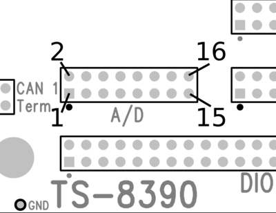
TS-8390-49xx ADC Header
The Microchip MCP3428 analog to digital converter consists of a 4-channel 16 bit sigma-delta converter and two, 2-channel analog switches. The ADC can be configured to 240hz 12-bit, 60hz 14-bit, or 15hz 16-bit samples. These are configured to allow input and conversion on two differential channels and 4 single ended channels. The 6-channel Analog to Digital signals are contained on connector HD5 which is a 16 pin (2x8) 0.1" spacing header. The connector layout and the signals carried by each pin are defined below. The input range for the differential input channels is 0- 2 VDC, and the input range on the single-ended channel is nominally 0-10 VDC.
The TS-4900 has example code for reading the ADC in the ts4900-utils git. https://github.com/embeddedTS/ts4900-utils/blob/master/src/adc8390.c
This command will configure the ADC to 16-bit samples (15sps) and dump all of the channels:
# adc8390 -r
adc0=409
adc1=52
adc2=0.000
adc3=0.000
adc4=3.360
adc5=2.742
