TS-TPC-7395
Disambiguation from TS-TPC-7395.
 | |
| Product Page | |
| Product Images | |
| Specifications | |
| Documentation | |
|---|---|
| Schematic | |
| Mechanical Drawing | |
| TS-TPC-7390/5 Mechanical Drawing | |
| FTP Path | |
| Processor | |
| Cirrus Logic EP9302 200MHz ARM9 (ARMv4T) | |
| CPU Datasheet |
Introduction
About this Manual
This manual is intended to provide the user with an overview of the board and benefits, complete features specifications, and set up procedures. It contains important safety information as well.
Feedback and Update to this Manual
To help our customers make the most of our products, we are continually making additional and updated resources available on the Technologic Systems website (www.embeddedTS.com).
These include manuals, application notes, programming examples, and updated software and firmware. Check in periodically to see what's new!
When we are prioritizing work on these updated resources, feedback from customers (and prospective customers) is the number one influence. If you have questions, comments, or concerns about your Embedded Computer, please let us know at support@embeddedTS.com.
Limited Warranty
See our Terms and Conditions for more details.
FCC Advisory Statement
This equipment generates, uses, and can radiate radio frequency energy and if not installed and used properly (that is, in strict accordance with the manufacturer's instructions), may cause interference to radio and television reception. It has been type tested and found to comply with the limits for a Class A computing device in accordance with the specifications in Subpart J of Part 15 of FCC Rules, which are designed to provide reasonable protection against such interference when operated in a commercial environment. Operation of this equipment in a residential area is likely to cause interference, in which case the owner will be required to correct the interference at his own expense.
If this equipment does cause interference, which can be determined by turning the unit on and off, the user is encouraged to try the following measures to correct the interference:
- Reorient the receiving antenna.
- Relocate the unit with respect to the receiver.
- Plug the unit into a different outlet so that the unit and receiver are on different branch circuits.
- Ensure that mounting screws and connector attachment screws are tightly secured.
- Ensure that good quality, shielded, and grounded cables are used for all data communications.
- If necessary, the user should consult the dealer or an experienced radio/television technician for additional suggestions.
The following booklets prepared by the Federal Communications Commission (FCC) may also prove helpful:
- How to Identify and Resolve Radio-TV Interference Problems (Stock No. 004-000-000345-4)
- Interface Handbook (Stock No. 004-000-004505-7)
These booklets may be purchased from the Superintendent of Documents, U.S. Government Printing Office, Washington, DC 20402.
Product Overview
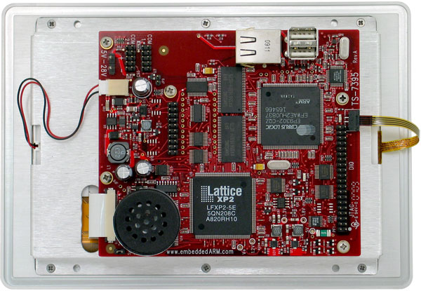
The TS-7390 is a RoHS compliant Single Board Computer (SBC) based on a Cirrus EP9302 200MHz ARM9 CPU, which provides a standard set of on-board peripherals such as 10/100 ethernet, USB, SD Card socket, digital I/O lines, temperature sensor, real time clock, and more. The TS-7390 features 64MB of SDRAM (128MB opt)
The TS-7390 features a 5,000 LUT on-board Lattice FPGA. The default FPGA load provides additional peripherals, such as SD Card socket and serial ports. A video core is included in the default load.
Benefits
Out-of-the-Box Productivity
Technologic Systems Linux products get you to your application quickly. Our Single Board Computers boot directly to Linux as shipped. There is no complicated CMOS setup or configuring of a Linux derivative Operating System to source, define, and load. The TS-7390's user can power up the board and immediately begin application development.
Of course, should you wish to configure your own version of Linux or use a different operating system, this is easy too. Technologic Systems provides the solution to fast application development without tedious OS configuration.
Impressive Performance
The ARM920T's 32-bit architecture, with a five-stage pipeline, delivers very impressive performance at very low power. The EP9302 CPU has a 16 KB instruction cache and a 16 KB data cache to provide zero-cycle latency to the current program and data, or they can be locked to guarantee no-latency access to critical sections of instructions and data. For applications with instruction-memory size restrictions, the ARM920Ts compressed Thumb instruction set can be used to provide higher code density and lower Flash storage requirements.
As a benchmark, the TS-7300's CPU integer performance, at a supplied 200 MHz, is about twice as fast as the Technologic Systems 133MHz 586-based products.
Features
The TS-7390 comes standard with these features:
- 200 MHz ARM9 CPU
- Up to 128MB DDR-RAM
- 5,000 LUT FPGA
- 10/100 Ethernet
- 3 RS-232, 2 RS-485, 1 TTL COM ports
- SD socket
- dual USB2.0 Full-Speed
- On-board framebuffer
Software features include:
- Unbrickable design
- Backward-compatible with TS-72xx boards
- Boots Linux in under 2 seconds
- Linux 2.6 and Debian
- Runs X11 (xorg) with icewm out of the box
Configurability
The TS-7390 can be configured for your application using the following available on-board options and external accessories:
On-Board Options
- OP-BBRTC: on-board sealed-battery backed RTC
- OP-TMPSENSE: High-precision temperature sensor
- OP-485-FD-14: RS-485 full duplex interface on COM2
- OP-485-HD-12: RS-485 half duplex interface on COM2
- OP-ROHS-NC: RoHS directive compliant built board
| Note: | The TS-7390 SBC can be built compliant with the RoHS (Restriction of Hazardous Substances ) Directive. Contact Technologic Systems for RoHS support. |
External Accessories
- SD-8GB-USB-LCDR: TS-LCD-READY bootable 8GB SD card with USB reader interface including recovery mechanism, out-of-the-box ECLIPSE IDE with debugging, ARM tool chain, Debian filesystem, Xorg, documentation and further binaries/utilities (supports TS-7350, TS-7370, TS-7390, (included in the KIT-LCDR)
- SD-512-LCDR : TS-LCD-READY bootable 512 MB SD card pre-installed with Debian Linux for ARM, Xorg and full tool chain (supports TS-7350, TS-7370, TS-7390, TS-7395)
- CB7-05: Null modem cable with a DB9F at each end (included in the KIT-LCDR)
- RC-DB9: 10-pin header COM port adapter cable to DB-9 (included in the KIT-LCDR)
- WIFI-G-USB: USB 802.11g wireless network interface
- TS-9445: Console Mini-Peripheral Board w/ 1 RC-DB9 cable (included in the KIT-LCDR)
- PS-5VDC-REG: International regulated 5VDC wall mounted Power Supply (incompatible with enclosure) (included in the KIT-LCDR)
In addition, a complete set of interfacing cables, connectors, and enclosures are available.
| Note: | Check our website at www.embeddedTS.com for an updated list of options and external accessories |
TS-LCD-READY Development Kit

The TS-LCD-READY Development Kit for the TS-7390 Single Board Computer includes all equipment necessary to boot into the operating system of choice and start working. The development kit is highly recommended for a quick start on application development.
The TS-LCD-READY Development Kit includes:
- SD Card with USB interface which includes:
- Complete Debian Linux distribution for ARM
- GNU GCC C/C++ compiler with full tool-chain enabling native application development
- Hardware test routines source code and other example source code
- Debian package system: apt-get, tasksel, dselect
- ECLIPSE IDE
- USB SD Card reader
- International regulated 5VDC wall mounted Power Supply
- TS-9445 Console board
- DB9+DB25 NULL modem cable
- Adapter cable from 10-pin header to DB9
- Various cables for connection DIO, LCD, Keypad, etc.
- Utility Media (SD Card) with complete source, manuals, example code, etc.
| Note: | Single board computer is not included in the Development Kit (sold separately). |
Software and Support
The ARM processor (the EP9302) comes from Cirrus and the platform is very similar to the Cirrus EDB9302 evaluation board. Cirrus has strongly promoted running Linux on this chip and has done most of the legwork in creating a patch set to the Linux 2.6 kernels, but we have also had to modify the Linux Kernel (TS-Kernel) so it can support NAND and NOR Flash chips (via mtd drivers), a compact flash IDE driver, A/D converters, SD Card through the TS-SDCORE, video, additional ethernet ports and more. If you want to use Linux and aren't tied to the x86 architecture, the TS-7390 can be very cost-effective.
The TS-7390 SBC's proprietary boot firmware makes it possible for the board to boot directly from NAND Flash and/or the SD Card, therefore the TS-7390's are shipped standard with the full-featured Debian Linux installed on the SD Card (busybox is installed in NAND Flash). Debian can also be used with an NFS root file system or USB flash drives. The TS-Kernel used is based upon the version 2.6.21, patched and compiled for the Cirrus EP9302 ARM920T processor. The EP3902 is Real-Time capable through the use of RTAI, please contact Technologic Systems for information about using RTAI in your application.
The root file system used by the Linux OS can be any of the following:
- JFS file system image on the fourth partition of an SD card
- NFS root, via Ethernet port(after fast bootup, one need to mount a NFS root and chroot to it)
Getting Started
Installation Procedure
Before performing any set up or placement procedures, take the precautions outlined in this section.
Handling the Board Safely
Be sure to take appropriate Electrostatic Discharge (ESD) precautions. Disconnect the power source before moving, cabling, or performing any set up procedures.
| WARNING: | Inappropriate handling may cause damage to the board. |
Setup and Installation Instructions
Follow these guidelines for safety and maximum product performance:
- Observe local health and safety requirements and guidelines for manual material handling
Setup Tools
Depending on placement and cabling, you may need the following tools:
- Small flat-blade screwdriver
- Small Phillips screwdriver
Setup Procedure
After locating, setting up, grounding, and cabling the TS-7390:
- Apply power
- Monitor the TS-7390 using a terminal emulator to verify that the board is operating properly
| Note: | Your board might include a screw power connector on the power input. Notice this connector is removable. Please pull this connector off before applying power. |
Disconnecting AC Power
- Unplug from the power source.
- Disconnect other cables as required.
Console and Power Up
The TS-7390 boot mechanism can boot from onboard NAND flash or SD card. If you did not purchase an SD card with your board, you can create a factory SD card using any 512MB or larger SD card. An SD card image is available here. When power is applied, the default boot behavior is fastboot, which provides a busybox prompt in under 2 seconds. When this shell is exited the board continues on to perform a full Debian boot (when SD card is inserted). This behavior is controlled by the linuxrc script, which by default is a symbolic link to linuxrc-fastboot. To automatically boot full Debian, link it instead to linuxrc-sdroot. Please note that changes made to files on the initial ramdisk are saved only in RAM. To save your changes permanently, type "save" at the fastboot prompt.
An ANSI terminal or a PC running a terminal emulator is required to communicate with your TS-7390 computer. Simply Attach the TS-9445 (these are included in the TS-LCD-READY Development Kit) to the JTAG/DIO header on the TS-7390, connect the 10 pin header COM adapter to the TS-9445 (Note the red wire on this cable needs to align with the white dot on the TS-9445), and use that to connect to your development PC with a DB9 cable using serial parameters of 115,200 baud, 8 data bits, no parity, no flow control, 1 stop bit (8N1). If you are running Linux, the minicom program works well, Windows XP and/or Vista users can run the Hyperterm application or download and run PuTTy. Technologic Systems offers a null modem cable with both 25 pin and 9 pin connectors at each end as part number CB7-05.
Connect a regulated 5-28VDC, (1A minimum) power source on the power input connector. Please note the polarity printed on the board. The boot messages, by default, are all displayed on COM1 at 115200 baud. The board will also answer telnet connections to IP address 192.168.0.50.
The TS-7390 board has Linux installed by default on onboard flash. Upon bootup, The board will boot within 1.24 seconds to a Linux prompt on UART #0 (/dev/ttyAM0).
The default fastboot shell has available several standard Linux commands through the "busybox" program. Technologic Systems has made several modifications to the busybox source code to keep bootup as fast and simple as possible. The modified source code is available to Technologic Systems customers.
Upon bootup, you should see out of your serial port when booting from a properly formatted SD card:
>> TS-BOOTROM - built Oct  1 2008
>> Copyright (c) 2008, Technologic Systems
>> Booting from onboard NAND flash...
.
.
.
Finished booting in 2.54 seconds
Type 'tshelp' for help
/ #
At this point, if you type 'exit' from the serial shell, the TS-7390 will then attempt a full Debian Linux bootup from the inserted SD card using partition #4 as the root file system. This version of Linux, an embedded version of Debian Linux, contains Apache, SSH, PPP, and FTP server and many other common utilities and libraries. Other community-supported embedded Linux distributions are available. For instance, the "Buildroot" project at http://buildroot.uclibc.org/ allows one to easily build custom filesystems and cross-toolchains.
Should the need arise to automatically bypass the fastboot and proceed directly into starting the SD card version of Linux, you can do so with the following command issued to the fastboot shell:
ln -sf /linuxrc-sdroot /linuxrc; save
To automatically boot from onboard flash the command is:
ln -sf /linuxrc-mtdroot /linuxrc; save
To automatically boot from USB flash dongle or USB hard drive:
The "check-usb-update" utility provides this feature and is included in the linuxrc files by default.
To get back to the fastboot shell at the next boot up, place the file "/fastboot" in the root directory of the filesystem:
touch /fastboot
The '/linuxrc' file is a shell script that is the very first thing run by the kernel on startup. Several sample startup scripts are included and can either be used directly ("ln -sf /linuxrc-XXX /linuxrc" command) or modified to include custom bootup logic. These shell scripts were designed to be as fast and simple as possible (approximately 45 lines of code) for easy customer modifications. It is anticipated that this shell script be modified from the default to implement things in the customer's product such as backup configurations, software field updates, conditional booting/verification of SD cards, etc. Technologic Systems professional services are available should you need help in implementing a specific feature.
TS-7390 Recovery
Although it is easy to get your board into an unbootable state during development if you botch a modification, it is equally easy to use an SD card to completely restore the onboard flash. First, a properly formatted SD card must be created, the latest image can be downloaded from https://files.embeddedTS.com/ts-arm-sbc/ts-7390-linux/binaries/ts-images/512mbsd-latest.dd.bz2 Please note that this image does not contain the Eclipse IDE that is distributed with SD cards from Technologic Systems. Once the image has been downloaded it can be copied to the SD card with the following command (assuming /dev/sda is the device where the SD card is located).
bzcat 512mbsd-latest.dd.bz2 | dd of=/dev/sda
or
bunzip2 512mbsd-latest.dd.bz2
dd if=512mbsd-latest.dd of=/dev/sda
Place a jumper on JP1 to make the TS-7390 boot from SD. Within a few seconds the board will have booted to a fastboot prompt from the SD card. The commands 'createmtdroot' and 'createmtdboot' can then be used to restore the onboard NAND flash to its factory settings.
Busybox Environment
After booting in about 2.54 seconds, the TS-7390 presents a Linux shell on the serial console. Standard Linux utilities are provided by the busybox program. Type 'help' for a list of provided utilities. Source code for the busybox utility is available on the Technologic Systems FTP site.
A shell subroutine file, ts7000.subr, will be in the root directory. This file is executed at startup and defines several convenient functions. Type 'tshelp' for a list of these features.
In addition, the following utility programs are installed on the TS-7390 by default:
- The save command will save the current initial ramdisk filesystem to the SD card partition 3. If you do not use the save command, then any changes made to the filesystem will not be permanent.
- The exit command will start full Linux boot or exit the telnet session.
- The createmtdroot command is useful for restoring a bricked TS-7390 or for cloning the software from one board to another. It erases the entire on-board flash, and then copies the kernel, initial ramdisk, and root filesystem from the SD card to the on-board flash. This assumes the board was booted from SD card.
- The createmtdboot command is like createmtdroot, but it copies only the kernel and initial ramdisk. It leaves partition 3 of the on-board flash intact.
- The sdmount command makes available executables on SD card at /mnt/root.
- The mtdmount command makes available NAND flash at /onboardflash directory.
- The peekpoke utility can be used to directly access memory space. This is recommended for low level hardware debugging. The ts7000.subr file shows examples of usage.
- The ts7350ctl utility is used to change and read MAC address, change CPU clock speed, and provide basic memory information. See section 5.3 for more information.
Loading or Transferring Files
Four methods are available for transferring files between a desktop PC and your TS-7390: Ethernet downloads, flash memory devices, Zmodem downloads, and NFS server. Full descriptions of each are detailed below. Other programs that use serial ports to transfer should work as well.
Transferring Files via the Ethernet Port
The default Linux root file system includes a small FTP server that can be used for uploading/downloading of files across an Ethernet network. Simply point your preferred FTP client to your TS-7390 IP address (default is 192.168.0.50). You can login as root or any valid user previously created from the useradd utility. By default, the TS-7390 will not accept anonymous FTP. With the SD card, a user named "eclipse" is present with password "eclipse".
Transferring Files via Flash Memory Device
An SD card or USB thumb drive can be used to easily move files from a host system. USB memory devices need no extra accessory to connect to the host PC. The flash memory devices can then be hot swapped (inserted or removed without rebooting the host PC). Mounting a USB drive on the TS-7390 can be done using the command:
mkdir /mnt/usbdrive && mount /dev/sda1 /mnt/usbdrive
Zmodem Downloads
Using the Zmodem protocol to send files to and from the TS-7390 SBC is simple and straightforward. The only requirement is a terminal emulation program that supports Zmodem, and virtually all do. If you are using Windows 95 or later for your development work, the HyperTerminal accessory works well.
To download a file to the TS-7390 from your host PC, execute lrz at the Linux command line on the TS-7390 (while using console-redirection from within your terminal emulator) and begin the transfer with your terminal emulator. In HyperTerminal, this is 'Send File...' from the 'Transfer' menu.
To upload a file from the TS-7390 to your host PC, execute lsz [FILENAME] at the Linux command line on the TS-7390 and start the transfer in your terminal emulator. Many emulators, HyperTerminal among them, will automatically begin the transfer themselves.
Occasionally there may be errors in transmission due to background operations. This is not a problem -- Zmodem uses very accurate CRC checks to detect errors and simply resends bad data. Once the file transfer is complete the file is completely error free. For best results when using HyperTerminal, the hardware handshaking must be enabled in HyperTerminal.
NFS Server
Although this method can be a bit more involved, it's the fastest and easiest way to transfer files to and from a development PC. Basically, setup a development PC running Linux and set it up as an NFS server to share a directory (see online documentation for accomplishing this such as this one on sourceforge). Mount the NFS server on a folder on the SBC and transfer files to and from that folder. You can even work directly in the folder. The command to mount an NFS server would look similar to this:
mkdir /mnt/nfsshare && mount -t nfs -o nolock,vers=2 192.168.1.100:/share /mnt/nfsshare
Software
Accessing internal TS-7390 registers from Linux userspace
Linux applications run in a protected and separate environment where they can do no damage to either the kernel or other applications running simultaneously. This protected environment does not allow arbitrary manipulation of hardware registers by default. Applications may be allowed temporary access through memory space windows granted by the mmap() system call applied to the /dev/mem device node. See example code for manipulating registers in the TS-7390 located at "https://files.embeddedTS.com/ts-arm-sbc/ts-7390-linux/samples".
When programming Linux applications that handle hardware devices on the TS-7390, it is important to understand the Memory Map of the EP9301 processor and additional hardware features. Each hardware device or functional component has its reserved memory address space, where the specific management registers are located.
Device drivers implementation is mostly reading and writing operations to specific memory registers. This is accomplished from the Kernel space through straight access to the physical memory. The resulting device driver provides high level procedures to the user so that one is able to talk to the hardware without knowing memory map, bits and such. Linux applications run in a protected and separate environment where they can do no damage to either the kernel or other applications running simultaneously. This protected environment does not allow arbitrary manipulation of hardware registers by default.
It is also possible to talk to hardware devices from user space. In doing so, one does not have to be aware of the Linux Kernel development process. The special "/dev/mem" device implements a way to access the physical memory from the protected user space, allowing readings and writings to any specific memory register. Applications may be allowed temporary access through memory space windows granted by the mmap() system call applied to the /dev/mem device node. For instance, to set up access to the GPIO registers at 0x12c00000 on the TS-7200, the following snippet of C code is provided as an example:
   #include <sys/mman.h>
   #include <sys/types.h>
   #include <sys/stat.h>
   #include <fcntl.h>
   {
      int fd = open("/dev/mem", O_RDWR|O_SYNC);
      char *gpioregs;
      gpioregs = (char *)mmap(0, 4096, PROT_READ|PROT_WRITE,
          MAP_SHARED, fd, 0x12c00000);
      gpioregs[0] xff; /* directions register set to all outputs */
      gpioregs[2] x12; /* output 1 to DIO_01 & DIO_4, all else 0 */
   }
An example program has been made available which demonstrates this principle by gathering data from the buffered inputs of the TS-7350 (which is practically identical to the TS-7390) here: getbufin.c
Some notes about the preceding code:
- Make sure to open using O_SYNC, otherwise you may get a cacheable MMU mapping which unless you know what you're doing, probably is not what you want when dealing with hardware registers.
- mmap() must be called only on pagesize (4096 byte) boundaries and size must at least have pagesize granularity.
- mmap() of /dev/mem is only allowed for processes with UID 0 (root)
- More information on mmap() and open() system calls can be had by running "man mmap" or "man open" from most any Linux shell prompt.
- When working with char * types to registers, make sure to compile with the "-mcpu=arm9" option otherwise the wrong ARM opcodes will be used and your byte reads/writes may be turned into 32-bit reads and writes
TS-7390 specific Linux devices
Although working with the TS-7390 Linux is identical in most ways to working with a PC version Linux, one does need to be aware of some driver differences.
The onboard flash is broken up into partitions and accessed through the Linux driver framework known as "MTD", or Memory Technology Device. The partitioning is dynamic and depends on the DOS-style MBR found at sector 0 of the flash. This MBR can be changed by using the "fdisk" command on the /dev/mtdblock/0 device, but doing so is not recommended.
/dev/mtdblock0 - Whole disk block device driver.
/dev/mtdblock1 - First MBR partition (bootloader kernel binary)
/dev/mtdblock2 - Second MBR partition (bootloader initrd)
/dev/mtdblock3 - Third MBR partition (Linux YAFFS2 filesystem)
The SD card has a slightly different partition scheme to facilitate usage on a host PC. The SD card shows up as /dev/tssdcarda.
/dev/tssdcarda1 - First MBR partition
(Formatted FAT32, SD card bought from Technologic Systems contains the Eclipse IDE)
/dev/tssdcarda2 - Second MBR partition (bootloader kernel binary)
/dev/tssdcarda3 - Third MBR partition (bootloader initrd)
/dev/tssdcarda4 - Fourth MBR partition (Linux JFS filesystem)
Note that the MBR installed by default on the TS-7390 contains a 446 byte bootloader program that loads the initial power-on kernel and initrd from the first and second partitions. Replacing it with a MBR found on a PC would not work as a PC MBR contains an x86 code bootup program.
Linux uses a NAND flash filesystem called YAFFS2 for general purpose file storage. This filesystem is a log-structured filesystem which is safe against corruption caused by system crashes and power loss without the need for consistency checking on next boot. A normal PC cannot use this filesystem as it is specifically designed for NAND flash which a PC does not have.
Debian Linux OS
The typical way of doing Linux development on the TS-7390 is actually on the board itself. Since the TS-7390 CPU is a PC-class processor in everything but power consumption and performance, it has no problem running real PC-class operating systems such as Linux. By running the full version of Linux (and not scaled-down microcontroller project OS's such as ucLinux), the TS-7390 can run the entire suite of applications contained in the Debian Linux distribution including the compilers. Since almost every open source program available for Linux is contained within the Debian Linux binary distribution, one rarely has to compile the large code-bases that would otherwise have forced integrators to a complicated cross-compilation environment due to the limited RAM/Mhz of the embedded computer. All too often, open-source projects do not anticipate the possibility of cross-compilation in their build systems, leaving issues for the system integrator to resolve.
The default SD card contains compilers and everything needed for developing applications in C, C++, PERL, PHP, and SH. Java, BASIC, TCL, Python and others are available for Debian, but not installed by default.
One can still use cross-compilers hosted on just about any platform if there is a specific need. Technologic systems includes binary versions of the popular Linux "crosstool" project at http://www.kegel.com/crosstool/ to allow cross-compiling on Windows/cygwin or a Linux/i386 PC on our website website.
apt-get
When using the Debian Linux file system, adding new packages and removing undesired ones is done all through Debian's package management. "apt", "dpkg", all behave as expected. With Debian, one can easily install and remove software packages. For a quick demonstration of how easy it is to remove and install programs with Debian, try the following commands:
apt-get update
apt-get install hexedit
hexedit /etc/passwd
^C (hit CTRL+C to safely exit)
apt-get remove hexedit
apt-get install installs a package name, while apt-get remove removes the named package. Visit the Debian home page for further information, since a full in-depth discussion on Debian is outside the scope of this document.
Please note that the TS-73x0 is based on Debian Etch, which has gone in to archive status. In order to correctly use the TS-73x0 to get packages from Debian, the file /etc/apt/sources.list needs to be modified to have the following line:
deb http://archive.debian.org/debian etch main
Make sure to perform an apt-get update before attempting any other apt commands.
Getting Started with Linux
Logging In
After the desired Linux Kernel is loaded and executed, the file system loads and networking, logging, Apache web server, etc. are all started. When the login prompt is displayed, type "root" to login, with no password. A Bash login prompt will then appear. At this point, you are ready to enjoy your TS-7390 SBC running Linux. If you are new to Linux, www.debian.org is a good starting point for the Debian distribution.
Shutdown
Use the "shutdown -h now" command to halt the Linux system when running from SD or USB memory card to avoid corruption issues. The SD card is formatted with a journaled filesystem and are highly tolerant of improper shutdown sequences. The "shutdown" or "poweroff" commands are not required but still recommended. Even the most robust filesystems are still prone to corruption if not gracefully shutdown.
General Linux Usage
For more information on using linux on the TS-7390, please refer to the Linux for ARM on TS-72XX guide on the Technologic Systems website.
Hardware Components
Processor
CPU Overview
The Cirrus EP9302 features an advanced 200 MHz ARM920T processor design with a memory management unit (MMU) that allows support for high-level operating systems such as Linux, Windows CE, and other embedded operating systems. The ARM core operates from a 1.8 V supply, while the I/O operates at 3.3 V with power usage between 100 mW and 750 mW (dependent on speed). As a general-purpose processor, it provides a standard set of peripherals on board. The ARM920T's 32-bit architecture, with a five-stage pipeline, consisting of fetch, decode, execute, memory, and write stages, delivers very impressive performance at very low power. The EP9302 CPU has a 16 KB instruction cache and a 16 KB data cache to provide zero-cycle latency to the current program and data, or they can be locked to guarantee no-latency access to critical sections of instructions and data. For applications with instruction-memory size restrictions, the ARM920Ts compressed Thumb instruction set can be used to provide higher code density and lower Flash storage requirements.
Cirrus EP9302 key features include:
- 200-MHz ARM920T Processor
- 16-kbyte Instruction Cache
- 16-kbyte Data Cache
- Linux®, Microsoft® Windows® CE-enabled MMU
- 100-MHz System Bus
- MaverickCrunch. Math Engine
- Floating point, Integer and Signal Processing Instructions.
- Optimized for digital music compression and decompression algorithms.
- Hardware interlocks allow in-line coding.
- MaverickKey. IDs
- 32-bit unique ID can be used for DRM-compliant, 128-bit random ID.
- Integrated Peripheral Interfaces
- 16-bit SDRAM Interface (up to 4 banks)
- 16-bit SRAM / FLASH / ROM
- Serial EEPROM Interface
- 1/10/100 Mbps Ethernet MAC
- Two UARTs
- Two-port USB 2.0 Full-speed Host (OHCI) (12 Mbits per second)
- IrDA Interface
- ADC
- Serial Peripheral Interface (SPI) Port
- 6-channel Serial Audio Interface (I2S)
- 2-channel, Low-cost Serial Audio Interface (AC'97)
- Internal Peripherals
- 12 Direct Memory Access (DMA) Channels
- Real-time Clock with Software Trim
- Dual PLL controls all clock domains.
- Watchdog Timer (SEE SECTION 4.4 Watchdog Timer)
- Two General-purpose 16-bit Timers
- One General-purpose 32-bit Timer
- One 40-bit Debug Timer
- Interrupt Controller
- Boot ROM
For further information on the Cirrus EP9302, refer to the Datasheet or User's Guide.
| Note: | The EP9302 is identical silicon to the EP9301 except it is rated to run at 200 Mhz, instead of 166 Mhz. The available EP9301 User's Guide can still be used as the main reference manual. |
MMU
The EP9032 features a Memory Management Unit, enabling high level operating systems such as Embedded Linux® and Windows® CE to run on the TS-7390. In the same way, the Linux TS-Kernel takes advantage of the MMU functionality. The MMU is controlled by page tables stored in system memory and is responsible for virtual address to physical address translation, memory protection through access permissions and domains, MMU cache and write buffer access. In doing so, software applications can access larger "virtual" memory space than the available physical memory size, allowing multiple programs to run and use the system memory simultaneously. For further information about the MMU functionalities, refer to the EP9302 User's Guide.
Interrupts
The EP9302 interrupt controller allows up to 54 interrupts to generate an Interrupt Request (IRQ) or Fast Interrupt Request (FIQ) signal to the processor core. Thirty-two hardware priority assignments are provided for assisting IRQ vectoring, and two levels are provided for FIQ vectoring. This allows time critical interrupts to be processed in the shortest time possible.
Internal interrupts may be programmed as active high or active low level sensitive inputs. GPIO pins programmed as interrupts may be programmed as active high level sensitive, active low level sensitive, rising edge triggered, falling edge triggered, or combined rising/falling edge triggered.
The EP9302 interrupt controller also includes the following features:
- Supports 54 interrupts from a variety of sources (such as UARTs, GPIO and ADC)
- Routes interrupt sources to either the ARM920Ts IRQ or FIQ (Fast IRQ) inputs
- Three dedicated off-chip interrupt lines operate as active high level sensitive interrupts
- Any of the 19 GPIO lines maybe configured to generate interrupts
- Software supported priority mask for all FIQs and IRQs
| Note: | For peripheral driver development purpose, notice that the external IRQ lines 5,6 and 7, which are ISA/X86 architecture based, are mapped to EP9302 external interrupt lines 22, 33 and 40, respectively. For further information about interrupts, including the EP9302 interrupt controller and map, refer to the EP9302 User's Guide, chapter 5. |
Memory
TS-7390 uses three types of memory. The SDRAM is the fast access volatile memory used to run applications by the processor, NAND flash is the non-volatile memory used to store the kernel and initrd, and flash memory may also be added using USB memory drivers.
On-Board SDRAM
The TS-7390 uses SDRAM technology to provide 64 or 128 MB of high-speed volatile memory. The memory is soldered directly to the board, making the TS-7390 more reliable in high-vibration environments.
The TS-7390's RAM is not contiguous in the physical memory map of the EP9302. But the MMU is programmed to remap the blocks of RAM to appear as a contiguous block of memory at the very beginning of the virtual memory map.
Refer to the MMU section of this manual to understand how the physical memory is mapped and the virtual memory is translated.
On-Board NAND Flash
The TS-7390 uses a 512MB NAND Flash chip for its on-board Flash resource. The physical address of the Flash chip is 0xe800_0800. The on-board flash is broken up into partitions and accessed through the Linux driver framework known as "MTD", or Memory Technology Device. The partitioning is dynamic and depends on the DOS-style MBR found at sector 0 of the flash. This MBR can be changed by using the "fdisk" command on the /dev/mtdblock/0 device, but doing so is not recommended.
USB Flash Drive or SD Card
Additional non-volatile storage may be added with a USB flash drive or a SD card. These devices supply additional non-volatile storage either for data or for a complete operation system distribution, such as Debian. A tar-file of Debian is available on the Technologic Systems website. Alternatively, the developer's kit includes a USB flash thumb-drive or SD card pre-loaded with Debian. Flash memory provided by these devices behaves much as a hard drive does with sizes ranging from 32MB to 16GB. These products are inherently more rugged than a hard drive since they are completely solid-state with no moving parts. However, they have the added advantage of being removable media. Use of a SD card with TS-7390 SBC requires a USB SD card adapter, which will also be included in the TS-LCD-READY Development Kit if requested. The USB flash drive has the advantage over a SD card in that the USB drive can be hot swapped.
SD Memory Card
Technologic Systems has a full license for using the additional SD features which are reserved for members of the SD Card Association. This has allowed us to design both the hardware logic core and software specifically tuned to the capabilities of the TS-7390 CPU using the official SD specification documents. Since both a Linux driver module and an ARM9 object file containing OS-independent access routines are provided to customers purchasing the board hardware, customers do not have to seek SD licensing themselves.
SD Memory Card technology provides large capacity and fast access combined with a compact and slim profile, making it very appealing for a wide range of next generation products and applications. In addition, SD Cards feature content protection, planned capacity growth, high-speed data transfer, and a write protect switch. These devices supply additional non-volatile storage either for data or for a complete operation system distribution, such as Debian, to be used with the TS-7390 SBC.
Real Time Clock
The TS-7390 optionally supports a Non-volatile Battery-backed real-time clock (RTC) which is soldered onto the board. This option uses an ST Micro M48T86PC1 module for the real-time clock function. This module contains the lithium battery, 32.768 kHz crystal, and a RTC chip with 114 bytes of battery-backed CMOS RAM. It will maintain clock operation for a minimum of 10 years in the absence of power.
The 114 bytes of non-volatile RAM, physically located in the RTC chip, are available to the user. Contact Technologic Systems for driver support.
The RTC can be accessed and setup through the hwclock command:
   / # hwclock --help
   hwclock - query and set the hardware clock (RTC)

   Usage: hwclock [function] [options...]

   Functions:
     --help        show this help
     --show        read hardware clock and print result
     --set         set the rtc to the time given with --date
     --hctosys     set the system time from the hardware clock
     --systohc     set the hardware clock to the current system time
     --adjust      adjust the rtc to account for systematic drift since
                   the clock was last set or adjusted
     --getepoch    print out the kernel's hardware clock epoch value
     --setepoch    set the kernel's hardware clock epoch value to the
                   value given with --epoch
     --version     print out the version of hwclock to stdout

   Options:
     --utc         the hardware clock is kept in coordinated universal time
     --localtime   the hardware clock is kept in local time
     --directisa   access the ISA bus directly instead of /dev/rtc
     --badyear     ignore rtc's year because the bios is broken
     --date        specifies the time to which to set the hardware clock
     --epoch=year  specifies the year which is the beginning of the
                   hardware clock's epoch value
     --noadjfile   do not access /etc/adjtime. Requires the use of
                   either --utc or --localtime
Watchdog Timer
The TS-7390 incorporates a Watchdog Timer (WDT) unit. The WDT can be used to prevent a system "hanging" due to a software failure. The WDT causes a full system reset when the WDT times out, allowing a guaranteed recovery time from a software error. To prevent a WDT timeout, the application must periodically "feed" the WDT by writing a specific value to a specific memory location.
The "ts7000.subr" shell function script provides an insight as to how to utilize the watchdog timer:
   wdt_on_338ms() {
     peekpoke 16 0x600ff0d6 0x0 > /dev/null 2>&1
   }

   wdt_on_2706ms() {
     peekpoke 16 0x600ff0d6 0x1 > /dev/null 2>&1
   }

   wdt_on_10824ms() {
     peekpoke 16 0x600ff0d6 0x2 > /dev/null 2>&1
   }

   wdt_on() {
     wdt_on_10824ms
   }

   wdt_off() {
     peekpoke 16 0x600ff0d6 0x3 > /dev/null 2>&1
   }
The WDT register (memory location 0x600ff0d6) must be re-initialized within the timeout period desired. This may be as short as 338 mS or may be as long as 10.824 seconds. After the WDT has been enabled, the WDT counter begins. The application software can reset this counter at any time by "feeding" the WDT. If the WDT counter reaches the timeout period, then a full system reset occurs.
| Value | MSB | MID | LSB | Timeout Period |
|---|---|---|---|---|
| 0x00 | 0 | 0 | 0 | 338 mS |
| 0x01 | 0 | 0 | 1 | 2706 mS |
| 0x02 | 0 | 1 | 0 | 10824 mS |
| 0x03 | 0 | 1 | 1 | Disable Watchdog |
| 0x04 | 1 | 0 | 0 | -- Reserved |
| 0x05 | 1 | 0 | 1 | -- Reserved |
| 0x06 | 1 | 1 | 0 | -- Reserved |
| 0x07 | 1 | 1 | 1 | -- Reserved |
| WARNING: | Use only the Watchdog Timer implemented by Technologic Systems in the CPLD. The Watchdog Timer included in the EP9302 has serious problems. |
Random Number Generator
The TS-7390 has a built-in true random number generator (RNG). The number is generated from internal random entropy. The 32-bit value at address 0x600f_f0d0 contains the most recent random value generated. Only thirty-two bits of true random data are created every second, so if this register is read more quickly the values read are not guaranteed to be random: in fact, you will either read the same value as previously or else a pseudo-random intermediate value from the last value generated.
Lattice FPGA
The 5,000 LUT Lattice FPGA is an integral part of the TS-7390 design. When the TS-7390 is powered on, the FPGA comes on first and it then boots the CPU, using boot code stored in internal flash and from either the on-board flash or the SD card. After an operating system has booted, the FPGA provides the CPU access to the SD cards, and the 40-pin connector. Due to the flexibility of FPGAs, many other functionalities are possible such as quadrature encoders, PWM outputs, extra serial ports, or other unique communications protocols. Please contact Technologic Systems if you require custom FPGA logic as the FPGA source is proprietary and not open source.
LEDs
LEDs
There are two LEDs on the TS-7390: one red and one green. Both LEDs comes on at power-up and and then turn off - the green light turns off quickly while the red LED fades off. The green and red LEDs are controlled through the CPU GPIO port E. They can be controlled using bits 0 and 1, respectively, of the port E register at address 0x8084_0020. For example, using "peekpoke 32 0x80840020 1" will turn the green LED on, whereas "peekpoke 32 0x80840020 0" will turn it off.
Jumpers
There is only one jumper on the TS-7390 near the speaker called JP1. This jumper forces the board to boot from the SD card, which is useful if the board has been bricked because it allows the user to reprogram the NAND flash.
Power Consumption
Unless otherwise specified, these are the testing parameters:
- Running at 12V
- No ethernet connected
- No USB peripherals connected
- Running at 200MHz
- Running from NAND
- Board includes RTC option
| Test | Max (W) | Average (W) |
|---|---|---|
| CPU 100% (LCD 100%) | 5.89 (0.491 A) | 5.46 (0.455 A) |
| CPU Idle (LCD 100%) | 5.89 (0.491 A) | 5.20 (0.433 A) |
| CPU Idle (LCD dim) [1] | 4.13 (0.344 A) | 3.67 (0.306 A) |
| CPU Idle (LCD 0%) [2] | 3.10 (0.258 A) | 2.58 (0.215 A) |
| CPU 166MHz (LCD 0%) [3] | 2.80 (0.233 A) | 2.45 (0.204 A) |
| CPU 41.5MHz (LCD 0%) [4] | 2.58 (0.215 A) | 2.34 (0.195 A) |
| CPU 14.7456MHz (LCD 0%) [5] | 2.44 (0.203 A) | 2.20 (0.183 A) |
| CPU 14.7456MHz (LCD 0%), CPU Eth Off [6] | 2.35 (0.196 A) | 2.06 (0.172 A) |
| CPU Idle (LCD 100%) + CPU Ethernet (near CPU) | 5.82 (0.485 A) | 5.36 (0.447 A) |
| CPU Idle (LCD 100%) + ASIX Ethernet (near power) | 5.96 (0.497 A) | 5.03 (0.419 A) |
- ↑ The LCD is dimmed with peekpoke 16 0x600FF086 0x7e02
- ↑ The LCD is off with peekpoke 16 0x600FF086 0x1e02
- ↑ Set with cpu_speed_166 subroutine in /ts7000.subr
- ↑ Set with cpu_speed_42 subroutine in /ts7000.subr
- ↑ Set with cpu_speed_min subroutine in /ts7000.subr
- ↑ Set eth off with eth_off subroutine in /ts7000.subr
Connectors and Headers
40 pin general header
The general header is a 40 pin (2x7, 0.1" spacing) header providing SPI, GPIO, latched outputs, buffered inputs, A/D inputs, an external reset line, and a console UART.
The general header is made up of two adjacent headers, labeled JTAG and DIO:
| 2 | 4 | 6 | 8 | 10 | 12 | 14 | 16 | 2 | 4 | 6 | 8 | 10 | 12 | 14 | 16 | 18 | 20 | 22 | 24 |
| 1 | 3 | 5 | 7 | 9 | 11 | 13 | 15 | 1 | 3 | 5 | 7 | 9 | 11 | 13 | 15 | 17 | 19 | 21 | 23 |
| JTAG | DIO | ||||||||||||||||||
The pins on the 40 pin header serve a variety of functions. Refer to the table below to see which pins are available for each functionality.
| Pin Number | Name | Function |
|---|---|---|
| JTAG 1 | JTAG_DOUT | Reserved |
| JTAG 2 | JTAG_TMS | Reserved |
| JTAG 3 | GND | Tied to ground |
| JTAG 4 | JTAG_DIN | Reserved |
| JTAG 5 | HGPIO_3 | DIO |
| JTAG 6 | JTAG_CLK | Reserved |
| JTAG 7 | UART0_TXD | UART0 |
| JTAG 8 | UART0_RXD | UART0 |
| JTAG 9 | SPI_MISO | SPI bus |
| JTAG 10 | 3.3V | Tied to 3.3V |
| JTAG 11 | HGPIO_5 | DIO |
| JTAG 12 | SPI_MOSI | SPI bus |
| JTAG 13 | FLASH_CS# | Reserved |
| JTAG 14 | SPI_CLK | SPI bus |
| JTAG 15 | 5V | Tied to 5V |
| JTAG 16 | EXT_RESET# | External reset |
| DIO 1 | SPI_FRAME | SPI bus |
| DIO 2 | GND | Tied to ground |
| DIO 3 | RSVD | Reserved |
| DIO 4 | OUT_5 | Latched output |
| DIO 5 | IN_00 | Buffered input |
| DIO 6 | OUT_4 | Latched output |
| DIO 7 | IN_01 | Buffered input |
| DIO 8 | OUT_3 | Latched output |
| DIO 9 | IN_02 | Buffered input |
| DIO 10 | OUT_2 | Latched output |
| DIO 11 | IN_03 | Buffered input |
| DIO 12 | OUT_1 | Latched output |
| DIO 13 | IN_04 | Buffered input |
| DIO 14 | OUT_0 | Latched output |
| DIO 15 | IN_05 | Buffered input |
| DIO 16 | ADC4/BGPIO_7 | ADC/DIO |
| DIO 17 | IN_06 | Buffered input |
| DIO 18 | BGPIO_6 | DIO |
| DIO 19 | BGPIO_5 | DIO |
| DIO 20 | ADC2/IN_07 | ADC/Buffered input |
| DIO 21 | I2C_SDA | I2C |
| DIO 22 | ADC1/IN_08 | ADC/Buffered input |
| DIO 23 | I2C_SCL | I2C |
| DIO 24 | ADC0/IN_09 | ADC/Buffered input |
| Note: | Please note: Pins labeled "reserved" are used at the factory for production purposes and should not be used for applications. |
Analog to Digital Conversion
Pins labeled ADC are available for analog to digital conversion using the Cirrus 5 channel A/D converter. Channels 0, 1, 2, and 4 are available for applications. Channel 3 is used internally.
Each of these pins, if not being used for A/D conversion, can instead be used as a buffered input, or in the case of pin DIO 16, a GPIO pin. For instructions on buffered inputs, please refer to the relevant section below.
TS-TPC-7390 ADC Sampling example: Uses ADC channel 2 (jtag header pin 36, DIO 20, IN_07).
/*
 * TS-TPC-7390 / TS-7390 EP9302 ADC test
 * Reads pin JTAG header pin 36: IN_07 / ADC2 / DIO20
 *
 * Compile on target:
 *   gcc -o read_adc2 read_adc2.c
 *
 * Run as root:
 *   ./read_adc2
 */

#include <stdio.h>
#include <stdlib.h>
#include <unistd.h>
#include <fcntl.h>
#include <sys/mman.h>

#define ADC_PHYS             0x80900000
#define SYSCON_PHYS          0x80930000
#define MAP_SIZE             4096

#define ADCRESULT_OFFSET     0x0008
#define ADCSWITCH_OFFSET     0x0018
#define ADCSWLOCK_OFFSET     0x0020

#define ADC_CH2              0x0640
#define ADC_SDR_MASK         0x80000000
#define ADC_DATA_MASK        0x0000ffff

#define ADCCLKDIV_OFFSET     0x0090
#define SYSCON_UNLOCK        0x00c0
#define DEVICECFG_OFFSET     0x0080

#define UNLOCK_VAL           0xaa
#define TSEN_MASK            0x80000000
#define ADCEN_MASK           0x00020000
#define ADCPD_MASK           0x00000004

#define REG32(base, off)     (*(volatile unsigned int *)((char *)(base) + (off)))

static void init_adc(void *syscon)
{
    unsigned int val;

    REG32(syscon, SYSCON_UNLOCK) = UNLOCK_VAL;
    val = REG32(syscon, ADCCLKDIV_OFFSET);
    val |= TSEN_MASK;
    val |= ADCEN_MASK;
    REG32(syscon, ADCCLKDIV_OFFSET) = val;

    REG32(syscon, SYSCON_UNLOCK) = UNLOCK_VAL;
    val = REG32(syscon, DEVICECFG_OFFSET);
    val &= ~ADCPD_MASK;
    REG32(syscon, DEVICECFG_OFFSET) = val;
}

static int read_adc_ch2(void *adc)
{
    unsigned int val;
    int timeout;

    REG32(adc, ADCSWLOCK_OFFSET) = UNLOCK_VAL;
    REG32(adc, ADCSWITCH_OFFSET) = ADC_CH2;

    usleep(2000);

    /* Reading ADCRESULT starts a conversion; discard old result. */
    (void)REG32(adc, ADCRESULT_OFFSET);

    /*
     * Modern driver notes the slow divisor path is about 925 samples/sec,
     * so wait a little over 1ms before polling.
     */
    usleep(1200);

    for (timeout = 0; timeout < 100000; timeout++) {
        val = REG32(adc, ADCRESULT_OFFSET);
        if (val & ADC_SDR_MASK)
            return (int)(val & ADC_DATA_MASK);
    }

    return -1;
}

int main(void)
{
    int fd;
    void *adc;
    void *syscon;
    int sample;

    fd = open("/dev/mem", O_RDWR | O_SYNC);
    if (fd < 0) {
        perror("open /dev/mem");
        return 1;
    }

    adc = mmap(NULL, MAP_SIZE, PROT_READ | PROT_WRITE, MAP_SHARED, fd, ADC_PHYS);
    if (adc == MAP_FAILED) {
        perror("mmap adc");
        close(fd);
        return 1;
    }

    syscon = mmap(NULL, MAP_SIZE, PROT_READ | PROT_WRITE, MAP_SHARED, fd, SYSCON_PHYS);
    if (syscon == MAP_FAILED) {
        perror("mmap syscon");
        munmap(adc, MAP_SIZE);
        close(fd);
        return 1;
    }

    init_adc(syscon);

    sample = read_adc_ch2(adc);
    if (sample < 0) {
        fprintf(stderr, "ADC timeout\n");
    } else {
        printf("ADC2 raw sample: %d\n", sample);
    }

    munmap(syscon, MAP_SIZE);
    munmap(adc, MAP_SIZE);
    close(fd);

    return sample < 0 ? 1 : 0;
}
Conversion to voltage is:
volts = (raw + 2500) * 3.3 / 50000.0;
DIO
Pins named "DIO" in the function column are connected directly to EP9302 GPIO pins. To use these pins, you must first set the data direction registers, and then read or write values from the data registers. When accessing these registers, it is important to do a read-modify-write, as other bits may be used internally. Pins named "BGPIO" are accessed through port B. The port B data direction register is located at address 0x80840014 and the port B data register is at 0x80840004. Pins named "HGPIO" are accessed through port H. The port H data direction register is located at address 0x80840044 and the port H data register is at 0x80840040. These pins are rated at 0v-3.3v and can safely source 4mA or sink 8mA.
Buffered Inputs
There are a total of 10 buffered digital input lines. Pins IN_0 through IN_6 are dedicated digital inputs, while pins IN_9 through IN_11 are in parallel with analog inputs and thus can only be used for digital input if analog inputs are not needed. Pins IN_0 through IN_3 have resistor pull-ups. The others will return random data if not driven high or low.
The 16 bit register at address 0x600f_f084 provides access to digital inputs. Pins IN_0 through IN_6 are accessed by bits 6 through 12. Pins IN_9 through IN_11 are accessed by bits 13 through 15.
See example source code for more information on how to use buffered inputs from within userspace: getbufin.c .
Latched Outputs
Pins OUT_0 through OUT_5 are digital output lines. The 16 bit register at address 0x600f_f084 provides access to digital outputs through bits 0 through 5. These pins are rated at 0v-3.3v and can safely source or sink 50mA.
UART0
UART0_TXD and UART0_RXD bring out the TTL level signals from the CPU. By default, this UART provides boot messages and the Linux console.
SPI Bus
The SPI_CLK, SPI_MOSI, SPI_MISO, and SPI_FRAME pins bring out the SPI bus from the EP9302 CPU. Please refer to the EP9302 user's guide for more information.
External Reset
Driving the external reset pin low will reset the CPU. While the JFS file system on the SD card is extremely resilient and is normally not damaged by hard resets, rebooting the board using the reboot command is still recommended if the file system is mounted read/write.
Temperature Sensor (optional)
The TS-7390 has an optional on-board temperature sensor (part #:OP-TMPSENSE). The temperature sensor used is a TMP124; a copy of the datasheet can be found here, and sample code can be found here.
The temperature sensor is accessed via SPI pins on the DIO header documented in the previous section. The DATA pin on the TMP124 is connected to the SPI_MISO# signal, while the CLK pin is connected to the SPI_CLK pin. In addition there is a chip select signal which must be asserted in order to use the temperature sensor chip. This signal is accessed through bit 2 of the register at address 0x80840030. (CPU GPIO port F) Note that the polarity of this signal is active high (set this bit to select the temp sensor).
Expansion Bus
The 20-pin header located next to the battery-backed real-time clock (or next to the pads if the RTC option is not installed) provides an expansion bus. Originally this was designed to talk directly to an SJ1000 (CAN) chip. The software interface consists of two 8-bit registers: an address register mapped at 0x600FF410 and a data register at 0x600FF414. Once an address is written, each read of the data register will cause a read bus cycle on the expansion bus and return the value read, and each write to the data register will cause a write bus cycle with the value written.
The pin diagram and the pin-out for the expansion bus is shown below:
| 2 | 4 | 6 | 8 | 10 | 12 | 14 | 16 | 18 | 20 | ||
| 1 | 3 | 5 | 7 | 9 | 11 | 13 | 15 | 17 | 19 | ||
| RTC side | |||||||||||
| Pin | Name | Function |
|---|---|---|
| 1 | BUS_IOR# | |
| 2 | BUS_IOW# | |
| 3 | BUS_TXD | |
| 4 | BUS_D3 | data bit 3 |
| 5 | BUS_D1 | data bit 1 |
| 6 | BUS_D2 | data bit 2 |
| 7 | BUS_D4 | data bit 4 |
| 8 | BUS_D5 | data bit 5 |
| 9 | BUS_D6 | data bit 6 |
| 10 | BUS_D0 | data bit 0 |
| 11 | BUS_RXD | |
| 12 | BUS_D7 | data bit 7 |
| 13 | IRQ7 | |
| 14 | 3.3V | 3.3V power rail |
| 15 | BUS_ALE | |
| 16 | NC | no connection |
| 17 | BUS_CS# | |
| 18 | CPU_RESET# | Reset signal |
| 19 | 5V | 5V power rail |
| 20 | GND | ground rail |
Signal names ending in "#" are active low.
The expansion bus is at offset 0x10 (address) and 0x14 (data) from the NAND registers, which are at offset 0x400 from base address of 0x600ff000.
Address Write Cycle
peekpoke 8 0x600ff410 0x55
          _
BUS_ALE__/ \___________________
          _____________________
BUS_D0 __/
Data Write Cycle
peekpoke 8 0x600ff414 0x55
           ____________________
BUS_D0  __/
        __   __________________
BUS_IOW#  \_/
        __   __________________
BUS_CS#   \_/
Data Read Cycle
peekpoke 8 0x600ff414
            ___________________
BUS_D0   __/
         _____   ______________
BUS_IOR#      \_/
         _____   ______________
BUS_CS        \_/
In this example, BUS_D0 is set up externally to the board.
| Note: | In the above examples, for simplicity only BUS_D0 is shown. For clarity in showing transition points, it is assumed that the pre-existing state of this bit will be opposite of the new value; this will not always be the case. |
UARTs
In addition to the serial console there are 6 additional serial ports. One is implemented in the EP9302 and the remaining ports are TS-UARTs. Under Linux the second EP9302 serial port is known as /dev/ttyAM1, and this port goes to the COM1 header.
The remaining TS-UARTs have Linux device names of /dev/tttsX, where X is the TS-UART number, starting with 0. The table below summarizes the TS-UART ports:
| # | RS- | base adrs | header | Tx / X+ | Rx / X- | TxEn | RTS | CTS |
|---|---|---|---|---|---|---|---|---|
| 0 | 232 | 0x600FF0A0 | COM2 | 3 (TXD) | 2 (RXD) | N/A | no | no |
| 1 | 232 | 0x600FF0A4 | COM1 | 7 (RTS) | 8 (CTS) | N/A | no | no |
| 2 | 232 | 0x600FF0A8 | COM1 | 4 (DTR) | 1 (DCD) | N/A | no | no |
| 3 | 485 | 0x600FF0AC | COM2 | 1 (DCD) | 6 (DSR) | auto | N/A | N/A |
| 4 | 485 | 0x600FF0B0 | COM2 | 4 (DTR) | 9 (RI) | auto | N/A | N/A |
| 5 | TTL | 0x600FF0B4 | expansion bus | 3 (BUS_TXD) | 11 (BUS_RXD) | N/A | no | no |
TS-UART registers are 16-bits wide.
11/01/2010 - Note there is an issue in our current shipping SD card image. The driver for TSUARTs only support the first 5 TSUARTs and do not initialize the 6th. You can find updated versions of tsuart1.ko and tsuart7350.ko on our FTP site. These simply need to be copied to the initrd (third SD card partition). This will be addressed in the next software release.
Audio Speaker
The TS-TPC-7390 provides audio capabilities via a mono speaker, which a codec that supports up to a 12kHz sample rate. The playsound utility is provide, both compiled into busybox and also as a standalone utility, which can play sounds to this speaker. It can play most types of sound file if the "sox" command is in the path, otherwise it just plays WAV files. The playsound utility will down-sample automatically as needed. Sound is played by writing samples to a 4096(x16 bit) sample buffer in the FPGA. The source code for playsound is available to illustrate how this is done.
Touch Screen LCD
The TS-TPC-7390 LCD panel is a WVGA (800x480) display with built-in touchscreen. The touchscreen provides 12-bit A/D samples for both X and Y axes, for a nominal resolution of 4096x4096. Calibration of the touch screen is stored in FPGA tag memory along with other data. The Linux touchscreen driver (drivers/input/ts_lcd.ko) provides raw data from the touch screen to the generic linux evdev driver which provides a standard interface in /dev/event0.
Sample code (tstest.c) is available which demonstrates how to use the LCD, either through the Linux device drivers, or via direct hardware access.
Backlight control is provided. The backlight can be enabled and dimmed. This is controlled through the 16-bit register at address 0x600FF086. Setting bit 14 turns on the backlight, while clearing it turns the backlight off. Setting bit 13 dims the backlight while clearing it undims it.
Video Core:
The LCD panel video core is based on the TS-7KV core. The register definitions for the FPGA registers and video RAM for the TS-7KV are used in the TS-7390. The base addresses are:
| FPGA registers | 0x600FF030 |
| Video RAM | 0x60100000 |
Touchscreen Registers:
The current location the touchscreen is being pressed can be read from the X and Y A/D registers at address 0x600FF040 and 0x600FF042, respectively. These registers are 16-bit, formatted as follows:
| bit(s) | description |
|---|---|
| 15:4 | inverted A/D value |
| 3:1 | unused |
| 0 | reading value (0 if no touch detected) |
It is recommended to debouncing the transition from invalid to value. This can be done by ignoring the first 40ms of readings after the valid bit transitions high, and resetting this timer whenever the valid bit transitions low.
The readings from the touch screen should be processed and calibrated using the following formulas:
x = ( (~X) >> 0xFFF - calib_x0 ) * 4096 / calib_dx;
y = ( (~Y) >> 0xFFF - calib_y0 ) * 4096 / calib_dy;
Tag Memory
There are 136 bytes of "tag memory" or FPGA internal flash used to store various configuration values. The structure of this storage area follows:
| offsets | description |
|---|---|
| 0-2 | last three bytes of board MAC address |
| 3 | sysinfo bit 7 = industrial grade bits 6:0 = reserved |
| 4-7 | born-on date (represented in seconds since 00:00:00 UTC, January 1, 1970 |
| 8-27 | ADC calibration values 5 A/Ds,2 signed 16-bit values per A/D (12-bits of resolution) first value is the 0V value, second is the 3.3V value |
| 28-35 | touch screen calibration values 16-bit values "calib_x0", "calib_dx", "calib_y0", "calib_dy" |
| 36-75 | available for user |
Calibration values are stored in little endian format. Sample code (tagmem.c) is available which demonstrates how to read and write to the tag memory.
JTAG Header
The JTAG header is used at the factory for programming the FPGA and CPLD. It is not available for JTAG debugging on the CPU. Using the JTAG pins to program the FPGA is not supported and not recommended.
Power Supply Connector
The TS-7390 requires regulated 5-28VDC at 2500 mA @ 500 MHz(maximum).
Be sure to use a regulated 5-28VDC power supply, preferably with current limiting to 1 to 3 Amps. A current limited supply is very forgiving of common errors during development. A PC power supply that may be capable of supplying 20 Amps or more is not recommended. It is possible to do irreversible damage to the TS-7390 if the polarity on the power leads is reversed.
SD Card Connectors
The SD Card socket (ALPS connector) at the back side of the TS-7390 enable SD Cards to be used as primary storage devices for the TS-7390. The hardware core implemented by Technologic Systems is integrated inside the on-board FPGA. Technologic Systems has written a binary Linux driver module and a set of generic, OS-independent read/write routines for accessing the SD flash inside of an ARM object (.ko) file. The linuxrc startup script assumes that partition 4 of the SD card contains a JFS filesystem. The SD socket is bootable and fully supports SDHC cards.
COM2 Header
The COM2 header brings out COM2, /dev/ttts0, with Tx and Rx on pins 3 and 2 at RS-232 levels. If the board was purchased with the RS-485 option, then the RS-485 ports are also available on this header as described in section 5.12. The pinout of this header is as follows:
| 6 | 7 | 8 | 9 | 10 |
| 1 | 2 | 3 | 4 | 5 |
DB9 Connector
The DB9 connector brings out 1 CPU serial port (COM1, /dev/ttyAM0, by default the Linux console) and 2 TSUARTs. Tx and Rx signals for COM1 are on pins 3 and 2. See section 5.1 for more information on TSUARTs. All signals are at RS-232 levels.
Environmental Specifications
To ensure optimum product operation you must maintain the operational environmental specifications:
- Ambient Temperature: -20° to +70° C (+85° C @ 166MHz)
- Relative Humidity: 0 to 90% relative humidity. Not to exceed 90% non-condensing.
| Note: | Refer to your product manual, or contact Technologic Systems if the environmental temperature of the location is in doubt. |
Further References
Documentation
- Linux for ARM on TS-72XX User's Guide
- TS-7390 Schematic
- TS-7390 Mechanical Drawing
- TS-9445 Schematic
Articles
Software Pages
Downloads
CPU User Guide and Datasheet
Appendix A: TS-7390 FGPA Register Map
By default the Lattice FPGA on the TS-7390 is loaded with a system controller core at base physical address 0x600F_F080. Add that base to the offsets below to access these registers. These registers are all 16 bits wide and should therefore be accessed with 16 bit writes.
   base + 0x00: Board ID reg (RO, reads 0xCDE) & FPGA Rev
   base + 0x04: GPIO, Buffered Inputs (40 Pin Header)
      bit 06-15: Buffered IN_0 through Buffered IN_09
      bit 00-05: Latched OUT_0 through Latched OUT_5
   base + 0x06: JP1, Backlight & Speaker Control, UART1, SD, 485, SPI Control
      bit 15: JP1_I
      bit 14: Backlight Enable
      bit 13: Dim Backlight
      bit 12: NAND_WPN
      bit 11: Speaker Enable
      bit 10: UART1 CTS
      bit 09: UART1 DCD
      bit 08: SD_BUSY_I
      bit 07: SD_IRQ_EN
      bit 06: 485 Full Duplex Control
      bit 05: UART1 RTS
      bit 04: UART1 DTR
      bit 03: SPI Clock
      bit 02: SPI_SI
      bit 01: SPI_CSN
      bit 00: SPI_SO
   base + 0x07 to 0x51: Reserved
   base + 0x50: 16-bits of random data changed every 1 second. (RO)
   base + 0x54: 16-bits of random data changed every 1 second. (RO)
   base + 0x56: Watchdog feed register (write only)
      write value 0x0: feed watchdog for another .338s (approx)
      write value 0x1: feed watchdog for another 2.706s (approx)
      write value 0x2: feed watchdog for another 10.824 (approx)
      write value 0x3: disable watchdog
FCC Advisory
This equipment generates, uses, and can radiate radio frequency energy and if not installed and used properly (that is, in strict accordance with the manufacturer's instructions), may cause interference to radio and television reception. It has been type tested and found to comply with the limits for a Class A digital device in accordance with the specifications in Part 15 of FCC Rules, which are designed to provide reasonable protection against such interference when operated in a commercial environment. Operation of this equipment in a residential area is likely to cause interference, in which case the owner will be required to correct the interference at his own expense.
If this equipment does cause interference, which can be determined by turning the unit on and off, the user is encouraged to try the following measures to correct the interference:
Reorient the receiving antenna. Relocate the unit with respect to the receiver. Plug the unit into a different outlet so that the unit and receiver are on different branch circuits. Ensure that mounting screws and connector attachment screws are tightly secured. Ensure that good quality, shielded, and grounded cables are used for all data communications. If necessary, the user should consult the dealer or an experienced radio/television technician for additional suggestions. The following booklets prepared by the Federal Communications Commission (FCC) may also prove helpful:
How to Identify and Resolve Radio-TV Interference Problems (Stock No. 004-000-000345-4) Interface Handbook (Stock No. 004-000-004505-7) These booklets may be purchased from the Superintendent of Documents, U.S. Government Printing Office, Washington, DC 20402.
Limited Warranty
See our Terms and Conditions for more details.
Product Change Notices
SDRAM Change
| Synopsis | Due to material availability, the SDRAM chip was changed to a new vendor. This change predicated the need for updated FPGA code. |
| Severity | Minor |
| Class | Informational |
| Affected | All TS-739x purchased after April, 2019. |
| Status | No action necessary. |
Description:
Due to a manufacturer EOL, a new SDRAM part was selected and qualified by Technologic Systems for use on the TS-739x SBCs. The new part requires a new FPGA binary for proper operation. TBD: Add link to pcs.embeddedTS.com notification.
Identification:
The affected TS-739x are identifiable by the name "Alliance" visible on the SDRAM chip.
Necessary Action: None. The FPGA on the TS-739x is programmed at time of build. No further action is necessary by the downstream developer.