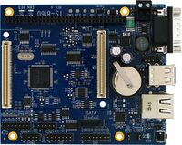
TS-8160-4200
 | |
| Released Mar. 2011 | |
| Product Page | |
| Documentation | |
|---|---|
| Schematic | |
| Mechanical Drawing |
Overview
The TS-8160 is a TS-SOCKET baseboard that provides an upgrade path for Technologic Systems TS-7260 and TS-7800 products. This board accepts any TS-4xxx macrocontroller. It interfaces to the macrocontroller via two TS-SOCKET standard 100-pin connectors and brings out the various ports to industry standard connectors. The TS-8160 is compatible with the TS-ENC720 enclosure.
TS-4200
See the TS-4200 page for functionality regarding the CPU, FPGA, and OS.

|
Atmel AT91SAM9G20 400MHz ARM9 |
Getting Started
Before attempting to apply power to the baseboard, perform the following steps while taking proper static discharge precautions
- Place the TS-8160 base board on a firm non-conductive surface.
- Place the COM1 "Console Enable" jumper in the console position so the debug port is brought out.
- Carefully, insert the macrocontroller daughterboard by aligning and pressing evenly and firmly onto the pair of mating connectors
- Connect the console serial terminal cable
- Connect the Ethernet cable is applicable.
- Apply power
- Monitor the TS-SOCKET SBC using a terminal emulator connected to the serial console port to verify that the board is operating properly
See the TS-4200 page for more details on dealing with the functionality of the macrocontroller.
Features
Software
The TS-8160 baseboards contains no processor or memory, and therefore do not have software on the board. All required software is supplied and executes on the selected Macrocontroller. There is a specific utility called ts8160ctl that runs on the attached Macrocontroller when paired with the TS-8160, and is used to set the sleep mode and sleep mode timing. There is no other software directly associated with the TS-8100/8160. The ts8160ctl is available here.
Register Map
All of these registers are intended for 16 bit access.
| Offset | Bits | Name | Access | Description |
|---|---|---|---|---|
| 0x0 | 15:0 | Board ID | Read Only | Returns '0x8100' |
| 0x2 | 3:0 | PLD revision | Read Only | |
| 7:4 | LCD Contrast | Read/Write | ||
| 8 | USB Reset | Read/Write | Allows you to reset the USB hub | |
| 9 | ISA Reset | Read/Write | ||
| 10 | Enable Oscillator | Read/Write | ||
| 11 | Enable RS-232 | Read/Write | ||
| 12 | Enable LCD Power | Read/Write | ||
| 13 | CAN1 Standby | Read/Write | ||
| 14 | CAN2 Standby | Read/Write | ||
| 15 | LCD Contrast Enable | Read/Write | ||
| 0x4 | 7:0 | Odd numbered pins 15:1 | Read/Write | Output data on the DIO header |
| 13:8 | PC104 pins A21:A16 | Read/Write | Output data on PC104 header | |
| 15:14 | PC104 pins B12:B11 | Read/Write | Output data on PC104 header | |
| 0x6 | 7:0 | Pins 14-7 data | Read Only | LCD data lines output data |
| 8 | LCD Write/Read (pin 6) | Read/Write | LCD Header pin 6 output data | |
| 9 | LCD Register Select (pin 3) | Read/Write | LCD Header pin 3 output data | |
| 10 | LCD Enable (pin 5) | Read/Write | LCD Header pin 5 output data | |
| 11 | AVR MOSI | Read/Write | ||
| 12 | AVR SCLK | Read/Write | ||
| 13 | AVR RESET | Read/Write | ||
| 14:15 | Reserved | N/A | ||
| 0x8 | 7:0 | DIO data direction (odd pins 15:1) | Read/Write | DIO Header data direction |
| 13:8 | PC104 pins A21:A16 | Read/Write | PC104 GPIO data direction | |
| 15:14 | PC104 pins B12:B11 | Read/Write | PC104 GPIO data direction | |
| 0xa | 7:0 | Pins 14-7 direction | Read Only | Set the data direction for the LCD GPIO |
| 8 | LCD Write/Read (pin 6) | Read/Write | Set the LCD Header pin 6 direction | |
| 9 | LCD Register Select (pin 3) | Read/Write | Set the LCD Header pin 3 direction | |
| 10 | LCD Enable (pin 5) | Read/Write | Set the LCD Header pin 5 direction | |
| 0xc | 7:0 | DIO Input Data (odd pins 15:1) | Read/Write | DIO Header input data |
| 13:8 | PC104 pins A21:A16 | Read/Write | PC104 GPIO input data | |
| 15:14 | PC104 pins B12:B11 | Read/Write | PC104 GPIO input data | |
| 0xe | 7:0 | Pins 14-7 data | Read Only | LCD Header input data |
| 8 | LCD Write/Read (pin 6) | Read/Write | For selecting between reads/writes | |
| 9 | LCD Register Select (pin 3) | Read/Write | Select between data and instruction registers | |
| 10 | LCD Enable (pin 5) | Read/Write | Toggles the LCD functionality | |
| 11 | AVR MISO | Read/Write | ||
| 15:12 | Reserved | N/A |