TS-DIO64: Difference between revisions
From embeddedTS Manuals
(Created page with "{{Infobox |title = TS-DIO64 |image = 300px |titlestyle = |headerstyle = background:#ccf; |labelstyle = width:33% |datastyle = |da...") |
No edit summary |
||
| Line 31: | Line 31: | ||
| Board identifier (returns 0xA4) | | Board identifier (returns 0xA4) | ||
|- | |- | ||
| rowspan=3 | 0x1 | |||
| 7:5 | | 7:5 | ||
| Read Only | | Read Only | ||
| Reserved | |||
|- | |- | ||
| 4 | | 4 | ||
| Line 44: | Line 44: | ||
| PLD Revision (1=REVA) | | PLD Revision (1=REVA) | ||
|- | |- | ||
| rowspan=5 | 0x2 | |||
| 7:5 | | 7:5 | ||
| Read/Write | | Read/Write | ||
| Line 70: | Line 70: | ||
| 0x3 | | 0x3 | ||
| 7:0 | | 7:0 | ||
| | | Read Only | ||
| Reserved | | Reserved | ||
|- | |- | ||
Revision as of 17:48, 25 July 2012
 | |
| Product Page | |
| Documents | |
|---|---|
| Schematic | |
| Mechanical |
Overview
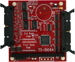
The TS-DIO64 is an 8-bit PC/104 (standard format) peripheral board that provides 64 digital I/O points (32 inputs plus 32 outputs) through two 34-pin locking connectors that are compatible with ribbon cables. Up to 4 TS-DIO64 boards may be installed into a single system, enabling up to 256 DIO points (128 inputs plus 128 outputs).
Register Map
| Address | Bits | Access | Description |
|---|---|---|---|
| 0x0 | 7:0 | Read Only | Board identifier (returns 0xA4) |
| 0x1 | 7:5 | Read Only | Reserved |
| 4 | Read Only | SRAM option present (1 = on) | |
| 3:0 | Read Only | PLD Revision (1=REVA) | |
| 0x2 | 7:5 | Read/Write | Reserved |
| 4 | Read/Write | Use SRAM in memory space (1 = enabled) | |
| 3:2 | Read/Write | SRAM memory address decode
0 = 0x0 1 = 0x20_0000 2 = 0x30_0000 | |
| 1 | Read Only | Battery status (1 = ok, 0 = bad) | |
| 0 | Read Only | External power status (1 = on) | |
| 0x3 | 7:0 | Read Only | Reserved |
| 0x4 | 7:0 | Read/Write | Output pins 1:8 |
| 0x5 | 7:0 | Read/Write | Output pins 9:16 |
| 0x6 | 7:0 | Read/Write | Output pins 17:24 |
| 0x7 | 7:0 | Read/Write | Output pins 25:32 |
| 0x8 | 7:0 | Read Only | Input pins 1:8 |
| 0x9 | 7:0 | Read Only | Input pins 9:16 |
| 0xa | 7:0 | Read Only | Input pins 17:24 |
| 0xb | 7:0 | Read Only | Input pins 25:32 |