TS-8100-4500
 | |
| Product Page | |
| Product Images | |
| Specifications | |
| TS-8100 | |
|---|---|
| Schematic | |
| Mechanical Drawing | |
| TS-4500 | |
| Schematic | |
| Mechanical Drawing | |
| FTP Path | |
| Processor | |
| Cavium CNS2312 250MHz ARM922 (ARMv4T) | |
| CPU Datasheet |
Overview
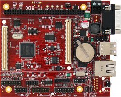
The TS-8100 baseboard is an upgrade path from our TS-7350/TS-7370 series providing a PC104 bus, multiple serial ports, LCD, and a DIO header.
Getting Started
A Linux workstation is recommended and assumed for development using this documentation. For users in Windows or OSX, we recommend virtualizing Linux. Most of our platforms run Debian, which is recommended for ease of use if there is no personal distribution preference.
Virtualization
Suggested Linux Distributions
Development using a Windows or OSX system may be possible but is not supported. Development will include accessing drives formatted for Linux and often Linux-based tools.
TS-8100 Options and Accessories
| Item | Description |

|
The TS-8100 is a TS-Socket Baseboard including a PC104 bus, DIO, RS232, RS485, and an optional second ethernet. |

|
The optional "OP-ETH" replaces the push button and instead populates a second ethernet port. This utilizes a USB ethernet which will work with any System-on-Module. |

|
The optional "OP-CAN2-485" includes the optional second #CAN and RS485 transceiver. |
| The option "OP-STHRU-64" includes a 64 pin PC104 connector that extends the pins so the TS-8100 does not need to be the base of the PC104 stack. This option is not required for stacking PC104 peripehral on the TS-8100 as the peripherals include a stack through connector. |
Other options include:
| Item | Description |
|---|---|

|
The RC-DB9 brings out the 10 pin connection to a DB9. See the RC-DB9 page for the exact pinout. The red line indicates pin 1 and should be lined up with the white dot on the board. |

|
The CB-USB-AF5P connects from a standard 5 pin 0.1" pitch header to a USB A host. This can be used to expose a single USB port while keeping the rest internal to your own enclosure. |

|
The CB7-05 is a 5 foot null modem cable. This is commonly used to connect to your workstation. |

|
The KPAD is a 4x4 keypad compatible with the DIO header on the TS-81XX. |
| KPAD-LCD | 2x24 Alphanumeric Display with 4x4 keypad mounted on a plate. |
Booting up the board
| WARNING: | Be sure to take appropriate Electrostatic Discharge (ESD) precautions. Disconnect the power source before moving, cabling, or performing any set up procedures. Inappropriate handling may cause damage to the board. |
The TS-8100-4500 accepts 5-28VDC input connected to the two terminal blocks.
 |
A typical power supply for just the TS-8100-4500 will allow around 1A, but a larger power supply may be needed depending on your peripherals.
Once you have applied power to your baseboard you should look for console output. Creating this connection is described more in the next chapter, but the first output is from the bootrom:
  >> TS-BOOTROM - built Dec 21 2011 10:05:44
  >> Copyright (c) 2011, Technologic Systems
  >> Booting from microSD card ...
  .
  .
  .
The 3 dots after indicate steps of the booting procedure. The first dot means the MBR was copied into memory and executed. The next two dots indicate that the MBR executed and the kernel and initrd were found and copied to memory.
The "Booting from XXXX...." message will indicate your boot media. On the TS-8100 this is controlled by the "SD Boot" jumper hear the ethernet connectors:

|
Get a Console
The TS-8100 console is an RS232 UART at 115200 baud, 8n1 (8 data bits 1 stop bit), and no flow control. On the TS-8100 you need to set the "Console Enable" jumper as pictured:

|
This will bring the console UART to both the DB9 Port, and the COM1 Header.
| Note: | If DIO_9 is held low during boot until the red LED comes on (around 5 seconds), console will be redirected to XUART 0. On most baseboards where this is applicable, DIO_9 is an exposed button. |
Console from Linux
There are many serial terminal applications for Linux, three common used applications are picocom, screen, and minicom. These examples demonstrate all three applications and assume that the serial device is "/dev/ttyUSB0" which is common for USB adapters. Be sure to replace the serial device string with that of the device on your workstation.
picocom is a very small and simple client.
sudo picocom -b 115200 /dev/ttyUSB0
screen is a terminal multiplexer which happens to have serial support.
sudo screen /dev/ttyUSB0 115200
Or a very commonly used client is minicom which is quite powerful but requires some setup:
sudo minicom -s
- Navigate to 'serial port setup'
- Type "a" and change location of serial device to "/dev/ttyUSB0" then hit "enter"
- If needed, modify the settings to match this and hit "esc" when done:
     E - Bps/Par/Bits          : 115200 8N1
     F - Hardware Flow Control : No
     G - Software Flow Control : No
- Navigate to 'Save setup as dfl', hit "enter", and then "esc"
Console from Windows
Putty is a small simple client available for download here. Open up Device Manager to determine your console port. See the putty configuration image for more details.


Initrd / Busybox
After the board is first booted you will be at this shell:
  >> TS-BOOTROM - built Oct 12 2011 13:35:38
  >> Copyright (c) 2009, Technologic Systems
  >> Booting from SD card...
  .
  .
  .
  >> Booted from: SD card                 Booted in: 3.93 seconds
  >> SBC Model number: TS-XXXX            SBC Sub-model number: 0
  >> CPU clock rate: 250MHz               RAM size: 64MB
  >> NAND Flash size: 256MB               NAND Flash Type: 0xdcec (Samsung)
  >> MAC number: 00:D0:69:4F:6F:04        SBC FPGA Version: 7
  >> Temperature Sensor: 37.500 degC      MODE1 bootstrap: ON
  >> RTC present: YES                     Date and Time: Jan  1 1970 00:00:03
  >> MODE2 bootstrap: OFF                 SD card size: 1886MB
  >> Offboard SPI flash type: Micron      Offboard SPI flash size: 8MB
  >> XUARTs detected: 3                   CAN present: NO
  >> Linux kernel version: 2.6.24.4       Linux kernel date: Jun 8 2011
  >> Bootrom date: Oct 12 2011            INITRD date: Dec 27 2011
  >> ts7500ctl date: Jun  8 2011          sdctl date: Jun  8 2011
  >> canctl date: Jun  8 2011             nandctl date: Aug 15 2011
  >> spiflashctl date: Aug 15 2011        xuartctl date: Aug 15 2011
  >> dioctl date: Feb 10 2011             spictl date: Jan 24 2011
  >> dmxctl date: Jun  8 2011             busybox date: Jun 30 2010 (v1.14.2)
  >> ts7500.subr date: Jun 10 2011        daqctl date: Aug 15 2011
  >> linuxrc date: Aug 31 2011            rootfs date: Jan  1 1970
  >> MBR date: Jul 14 2009

  Type 'tshelp' for help
  #
| Note: | Your version dates may be different depending on ship date and the image used. On newer units, "Offboard SPI" and "Onboard SPI" flashes may show "unknown" for the type. This is purely cosmetic and is no cause for concern. The SPI flash can be queried with the 'spiflashctl' tool which will return a proper manufacturer and device ID. |
This is a busybox shell which presents you with a very minimalistic system. While this has access to many Debian applications, it is important to note that this is not Debian. This environment will allow very fast boot times closer to 2-4 seconds, while Debian takes closer to 30-45 seconds but provides an init system and a more standard environment. As described in the previous section, the kernel and initrd are copied into RAM so any changes to this filesystem are temporary. You can commit changes using the "save" command.
For most development you will want to boot to the Debian filesystem which can be reached by typing "exit" through the serial console, or by relinking the linuxrc script to make the board automatically boot to Debian:
rm linuxrc; ln -s /linuxrc-sdroot /linuxrc; save
The linuxrc-sdroot script will actually mount and boot to the Debian filesystem on the SD or XNAND depending which device you used to boot. You can boot to a different Debian partition by using one of the other linuxrc scripts:
| Script | Function |
|---|---|
| linuxrc-fastboot (default) | Boots immediately to a shell in ramdisk. This will mount whichever boot medium you have selected to /mnt/root/. When you type 'exit', it will boot to that medium. |
| linuxrc-nandmount | Same as the linuxrc-fastboot script, but will mount and boot the debian partition from NAND. |
| linuxrc-sdmount | Same as the linuxrc-fastboot script, but will mount and boot the debian partition from SD. |
| linuxrc-sdroot | Boots immediately to the Debian stored on either SD or NAND depending on which media the SBC was booted from. |
| linuxrc-sdroot-readonly | Same as linuxrc-sdroot, except it will mount the Debian partition read only while creating a unionfs with a ramdisk. Changes will only happen in memory and not on disk. |
| linuxrc-usbroot | Mounts the first partition of the first detected USB mass storage device and boots there. |
Once you have booted to Debian you can force the boot process to stop in the fastboot shell/initd on next bootup with:
touch /fastboot
The small default initrd is only 2Mbyte but there is space for approximately 800 Kbyte of additional user applications. This constraint is important if you are running your application without Debian, but only from the initrd. If you have the Debian partition available you can access that partition under /mnt/root/ to run your application.
The compiled instance of busybox includes several internal commands listed below:
   # /bin/busybox --help
   BusyBox v1.14.2 (2009-08-07 14:43:48 MST) multi-call binary
   Copyright (C) 1998-2008 Erik Andersen, Rob Landley, Denys Vlasenko
   and others. Licensed under GPLv2.
   See source distribution for full notice.

   Usage: busybox [function] [arguments]...
      or: function [arguments]...

           BusyBox is a multi-call binary that combines many common Unix
           utilities into a single executable.  Most people will create a
           link to busybox for each function they wish to use and BusyBox
           will act like whatever it was invoked as!

   Currently defined functions:
           [, [[, ash, basename, cat, chgrp, chmod, chown, chroot, cmp, cp,
           cpio, cttyhack, cut, date, dd, depmod, devmem, df, dirname, dmesg,
           du, echo, egrep, env, expr, false, fdisk, fgrep, find, grep, gunzip,
           gzip, halt, head, hostname, hush, ifconfig, insmod, kill, killall,
           ln, login, ls, lsmod, md5sum, mdev, mkdir, mknod, modprobe, more,
           mount, msh, mv, netstat, ping, pivot_root, poweroff, printf, ps,
           pwd, reboot, rm, rmdir, rmmod, route, rx, sed, setconsole, setsid,
           sh, sleep, stty, sync, tail, tar, telnetd, test, tftp, top, tr,
           true, udhcpc, umount, unzip, usleep, uudecode, uuencode, vi, wget,
           xargs, yes, zcat
Also on the initrd are the TS specific applications: sdctl, spiflashctl, nandctl, daqctl, ts7500ctl, canctl, and xuartctl. We also provide the ts7500.subr which provides the following functions:
 cvtime()
 usbload()
 sdsave()
 spiflashsave()
 save()
 sd2spiflash()
 spiflash2sd()
 setdiopin()
 getdiopin()
 setrelay()
 setout()
 getin()
 tshelp()
 gettemp()
To use these functions you must source the subr file:
. /ts7500.subr
## or from Debian
# . /initrd/ts7500.subr
tshelp
System Configuration
For development it is recommended to go boot to the full Debian where there is plenty of space for development work. Debian provides many more packages and a much more familiar environment for users already versed in Debian. Once here you can use apt-get to install/remove packages, configure the network, and perform other common tasks.
Configuring the Network
From almost any Linux system you can use "ip" or the ifconfig/route commands to initially set up the network. To configure the network interface manually you can use the same set of commands in the initrd or Debian.
# Bring up the CPU network interface
ifconfig eth0 up

# Or if you're on a baseboard with a second ethernet port, you can use that as:
ifconfig eth1 up

# Set an ip address (assumes 255.255.255.0 subnet mask)
ifconfig eth0 192.168.0.50

# Set a specific subnet
ifconfig eth0 192.168.0.50 netmask 255.255.0.0

# Configure your route.  This is the server that provides your internet connection.
route add default gw 192.168.0.1

# Edit /etc/resolv.conf for your DNS server
echo "nameserver 192.168.0.1" > /etc/resolv.conf
Most commonly networks will offer DHCP which can be set up with one command:
Configure DHCP in Debian:
# To setup the default CPU ethernet port
pump -i eth0
# Or if you're on a baseboard with a second ethernet port, you can use that as:
pump -i eth1
Configure DHCP in the initrd:
udhcpc -i eth0
# Or if you're on a baseboard with a second ethernet port, you can use that as:
udhcpc -i eth1
To make your network settings take effect on startup in Debian, edit /etc/network/interfaces:
 # Used by ifup(8) and ifdown(8). See the interfaces(5) manpage or
 # /usr/share/doc/ifupdown/examples for more information.

 # We always want the loopback interface.
 #
 auto lo
 iface lo inet loopback

 auto eth0
 iface eth0 inet static
   address 192.168.0.50
   netmask 255.255.255.0
   gateway 192.168.0.1
 auto eth1
 iface eth1 inet dhcp
In this example eth0 is a static configuration and eth1 receives its configuration from the DHCP server. For more information on network configuration in Debian see their documentation here.
To make your changes permanent in the initrd you will need to edit the linuxrc script. Use the same commands you would use to manually configure it and place them over the current ifconfig calls.
Installing New Software
Debian provides the apt-get system which lets you manage prebuilt applications. Before you do this you need to update Debian's list of package versions and locations. This assumes you have a valid network connection to the internet.
Debian Lenny has been moved to archive so you will need to update /etc/apt/sources.list to contain these two lines:
 deb http://archive.debian.org/debian lenny main
 deb-src http://archive.debian.org/debian lenny main
Now you can update the local cache of packages:
apt-get update
For example, if you wanted to install picocom you could use the apt-cache command to search the local cache of Debian's packages.
 root@ts7500:~# apt-cache search picocom
 picocom - minimal dumb-terminal emulation program
You can often find the names of packages from Debian's wiki or from just searching on google as well.
Once you have the package name you can use apt-get to install the package and any dependencies. This assumes you have a network connection to the internet.
apt-get install picocom
# You can also chain packages to be installed
apt-get install picocom nano vim
For more information on using apt-get refer to Debian's documentation here.
Setting up SSH
On our boards we include the Debian package for openssh-server, but we remove the automatically generated keys for security reasons. To regenerate these keys:
dpkg-reconfigure openssh-server
Make sure your board is configured properly on the network, and set a password for your remote user. SSH will not allow remote connections without a password or a shared key.
passwd root
You should now be able to connect from a remote Linux or OSX system using "ssh" or from Windows using a client such as putty.
802.11 Wireless Network
This board optionally supports 802.11 through the #WIFI-N-USB module which will create the interface ra0 using the rt3070sta module. You can load this by running:
modprobe rt3070sta-7500
Scan for a network
ifconfig ra0 up

# Scan for available networks
iwlist ra0 scan
In this case I'm connecting to "default" which is an open network:
          Cell 03 - Address: c0:ff:ee:c0:ff:ee
                    Mode:Managed
                    ESSID:"default"
                    Channel:2
                    Encryption key:off
                    Bit Rates:9 Mb/s
To connect to this open network:
iwconfig ra0 essid "default"
You can use the iwconfig command to determine if you have authenticated to an access point. Before connecting it will show something similar to this:
# iwconfig ra0
rausb0    RT73 WLAN  ESSID:off/any  Nickname:""
          Mode:Auto  Frequency=2.412 GHz  Bit Rate:54 Mb/s
          RTS thr:off   Fragment thr:off
          Encryption key:off
          Link Quality=0/100  Signal level:-121 dBm  Noise level:-115 dBm
          Rx invalid nwid:0  Rx invalid crypt:0  Rx invalid frag:0
          Tx excessive retries:0  Invalid misc:0   Missed beacon:0
If you are connecting using WEP, you will need to define a network key:
iwconfig ra0 essid "default" key "yourpassword"
If you are connecting to WPA, you will need to use wpa_passphrase and wpa_supplicant:
wpa_passphrase the_essid the_password > /etc/wpa_supplicant_custom.conf
You will need to edit the /etc/wpa_supplicant_custom.conf file so the network block contains "proto=RSN". For example:
  network={
        ssid="default"
        proto=RSN
        #psk="yourpassword"
        psk=your-key-encoded
  }
The default image contains a patched wpa_supplicant for an older device, but for the WIFI-N-USB you will need to remove this and use the version from Debian:
mv /usr/local/bin/wpa_supplicant /usr/local/bin/wpa_supplicant.old
apt-get update && apt-get install wpasupplicant #This assumes a proper internet connection is established

# reset the shell to find the new wpa_supplicant
exec bash

# Verify that it is the correct version (0.6.4):
wpa_supplicant -v
Now that you have the configuration file, you will need to start the wpa_supplicant daemon:
wpa_supplicant -irausb0 -Dralink -c/etc/wpa_supplicant_custom.conf -B
When you have successfully connected, it will list an "Access Point" bssid, and a "Link Quality" of greater than 0/100.
# iwconfig rausb0
rausb0    RT73 WLAN  ESSID:"default"  Nickname:""
          Mode:Managed  Frequency=2.417 GHz  Access Point: c0:ff:ee:c0:ff:ee
          Bit Rate=11 Mb/s
          RTS thr:off   Fragment thr:off
          Encryption key:off
          Link Quality=63/100  Signal level:-70 dBm  Noise level:-99 dBm
          Rx invalid nwid:0  Rx invalid crypt:0  Rx invalid frag:0
          Tx excessive retries:0  Invalid misc:0   Missed beacon:0
Now you are connected to the network, but this would be close to the equivilant of connecing a network cable. To connect to the internet or talk to your internal network you will need to configure the interface. See the #Configuring the Network for more information.
Starting Automatically
From Debian the most straightforward way to add your application to startup is to create a startup script. This is an example simple startup script that will toggle the red led on during startup, and off during shutdown. In this case I'll name the file customstartup, but you can replace this with your application name as well.
Edit the file /etc/init.d/customstartup to contain this:
 #! /bin/sh
 # /etc/init.d/customstartup

 case "$1" in
   start)
     /usr/local/bin/ts7500ctl --redledon
     ## If you are launching a daemon or other long running processes
     ## this should be started with
     # nohup /usr/local/bin/yourdaemon &
     ;;
   stop)
     /usr/local/bin/ts7500ctl --redledoff
     ;;
   *)
     echo "Usage: customstartup start|stop" >&2
     exit 3
     ;;
 esac

 exit 0
| Note: | The $PATH variable is not set up by default in init scripts so this will either need to be done manually or the full path to your application must be included. |
To make this run during startup and shutdown:
update-rc.d customstartup defaults
To manually start and stop the script:
/etc/init.d/customstartup start
/etc/init.d/customstartup stop
To make your application startup from the initrd you only need to add the required lines (no need for the Debian init syntax) to the linuxrc script. Usually the best place to add in your application is right after /mnt/root/ is mounted so the Debian libraries and applications are available.
Backup / Restore
If you are using a Windows workstation there is no support for writing directly to block devices. However, as long as one of your booting methods still can boot a kernel and the initrd you can rewrite everything by using a usb drive. This is also a good way to blast many stock boards when moving your product into production. You can find more information about this method with an example script here.
MicroSD Card

|
Click to download the latest 2GB SD card image. |
Once downloaded you can decompress the image using bzip2:
bzip2 -d 2gbsd-noeclipse-latest.dd.bz2
The resulting file will be "2gbsd-noeclipse-latest.dd".
For imaging the SD card we recommend using a Linux or similar operating system that allows you to access a block device using dd. We do not support rewriting the SD card from Windows.
If you are reprogramming the SD card from your workstation you will also need to determine the SD card device. Once you have connected the SD card to your workstation you can usually find the correct block device in the output of "dmesg". For example:
 [  309.498834] sd 8:0:0:0: [sdb] 3862528 512-byte logical blocks: (1.97 GB/1.84 GiB)
 [  309.519814] sd 8:0:0:0: [sdb] Write Protect is off
 [  309.519818] sd 8:0:0:0: [sdb] Mode Sense: 03 00 00 00
 [  309.519819] sd 8:0:0:0: [sdb] Assuming drive cache: write through
 [  309.536025] sd 8:0:0:0: [sdb] Assuming drive cache: write through
 [  309.536029]  sdb: sdb1 sdb2 sdb3
 [  309.559672] sd 8:0:0:0: [sdb] Assuming drive cache: write through
 [  309.559676] sd 8:0:0:0: [sdb] Attached SCSI removable disk
On this system my SD card block device is /dev/sdb, but your system will likely be different. The block devices are allocated in order by the letter so the next USB drive connected would be /dev/sdc. On some newer kernels you will see '/dev/mmcblk0' as the block device and '/dev/mmcblk0p1' for the first partition. For these examples I will use the '/dev/mmcblk0' format.
| WARNING: | Many distributions will name your hard drive something like /dev/sda or /dev/hda which will have the same naming scheme as an SD card or a USB drive. Make sure you are aware which device is which before writing the disk. Technologic Systems is not responsible for any data lost/destroyed because of improper command execution. |
| WARNING: | If you are working with the SD card from your workstation, keep in mind that most Linux distributions will mount the partitions that they can as soon as the drive is inserted. This is desirable if you want to open the filesystem, but for dealing directly with the block device for performing backups or restoring an image this is dangerous to your data. |
To verify if your workstation has mounted the block device on insertion:
cat /proc/mounts
# look for your SD card block device to see if this is already mounted.
If the block device did automatically mount, you will need to refer to your distribution's documentation for disabling automounting. For example, this is Ubuntu's documentation on disabling automounting. If you are not using a graphical Linux system this should not be a concern, but make sure no filesystems are mounted read only or read write while writing or reading an image.
For backing up or restoring any images from the board you will need to make sure you do not have any partitions mounted. On the default configuration you can write an image from the initrd after unmounting /mnt/root:
umount /mnt/root/
Restore from Workstation
To write the latest image or restore to stock you would use the dd command. This will perform a byte for byte copy from our image. This contains the MBR boot code with the partition tables, the kernel, initrd, and Debian filesystem. No other formatting or partitioning is needed.
Write an image to the entire SD card:
dd if=/path/to/backup.dd of=/dev/mmcblk0 bs=4M conv=fsync
If you want to write a new kernel, but not an entire image you can rewrite the second partition:
dd if=/path/to/zImage bs=4M of=/dev/mmcblk0p2 conv=fsync
Backup from Workstation
To backup an entire SD card image:
dd if=/dev/mmcblk0 of=/path/to/backup.dd bs=4M
This will create a dd file the size of the card.
| Note: | A MicroSD card from one manufacturer will likely not be the exact same size as another manufacturer's MicroSD card of the same size. Our partition layouts by default leave the last 10% of the images unallocated to account for the size difference of various manufacturers MicroSD cards. As long as you use our partition layout you should not need to be concerned with this, but if you create your own layout we strongly recommend leaving 10% of the disk unallocated. |
Once you have the disk image you will want to trim this to the last partition so the image doesn't contain the free space at the end of the disk. To get the last sector you would use fdisk:
 fdisk -ucl /dev/sdb

 Disk /dev/sdb: 1977 MB, 1977614336 bytes
 61 heads, 62 sectors/track, 1021 cylinders, total 3862528 sectors
 Units = sectors of 1 * 512 = 512 bytes
 Sector size (logical/physical): 512 bytes / 512 bytes
 I/O size (minimum/optimal): 512 bytes / 512 bytes
 Disk identifier: 0x00000000

    Device Boot      Start         End      Blocks   Id  System
 /dev/sdb1             512        8703        4096   83  Linux
 /dev/sdb2            8704       15871        3584   da  Non-FS data
 /dev/sdb3           16896       20991        2048   da  Non-FS data
 /dev/sdb4           25088     3170815     1572864   83  Linux
On this SD card the end of the partition is 3170815 sectors. As the sectors each contain 512B the image is 1623457280 bytes. You can use the truncate command to correct the image size:
# This is an example - check your image with fdisk
truncate backup.dd --size=1623457280
Keep in mind these numbers are an example and are not necessarily representative of your image.
If you would like to backup just the Kernel partition, you would grab partition 2.
dd if=/dev/mmcblk0p2 of=/path/to/zImage bs=32k
Restore From the SBC
To write the latest image or restore to stock you would use the dd command. This will perform a byte for byte copy from our image. This contains the MBR boot code with the partition tables, the kernel, initrd, and Debian filesystem. No other formatting or partitioning is needed.
Write an image to the entire SD card:
dd if=/path/to/image-latest.dd of=/dev/nbd9 conv=fsync
Kernel
dd if=/mnt/root/zImage of=/dev/nbd7 conv=fsync
Backup From the SBC
To backup an entire SD card image:
# Determine the block size
eval $(sdctl)
dd if=/dev/nbd5 of=/path/to/backup.dd bs=512 count=$cardsize_sectors conv=sync && sync
This will create an image file the size of the card.
| Note: | A MicroSD card from one manufacturer will likely not be the exact same size as another manufacturer's MicroSD card of the same size. Our partition layouts by default leave the last 10% of the images unallocated to account for the size difference of various manufacturers MicroSD cards. As long as you use our partition layout you should not need to be concerned with this, but if you create your own layout we strongly recommend leaving 10% of the disk unallocated. |
Once you have the disk image you will want to trim this to the last partition so the image doesn't contain the free space at the end of the disk. To get the last sector you would use fdisk:
 fdisk -ucl /dev/sdb

 Disk /dev/sdb: 1977 MB, 1977614336 bytes
 61 heads, 62 sectors/track, 1021 cylinders, total 3862528 sectors
 Units = sectors of 1 * 512 = 512 bytes
 Sector size (logical/physical): 512 bytes / 512 bytes
 I/O size (minimum/optimal): 512 bytes / 512 bytes
 Disk identifier: 0x00000000

    Device Boot      Start         End      Blocks   Id  System
 /dev/sdb1             512        8703        4096   83  Linux
 /dev/sdb2            8704       15871        3584   da  Non-FS data
 /dev/sdb3           16896       20991        2048   da  Non-FS data
 /dev/sdb4           25088     3170815     1572864   83  Linux
On this SD card the end of the partition is 3170815 sectors. As the sectors each contain 512B the image is 1623457280 bytes. You can use the truncate command to correct the image size:
# This is an example - check your image with fdisk
# truncate is a Debian command and will not be available from busybox
truncate backup.dd --size=1623457280
Keep in mind these numbers are an example and are not necessarily representative of your image.
If you would like to backup just the kernel partition, you would grab partition 2.
dd if=/dev/mmcblk0p2 of=/path/to/zImage bs=32k
XNAND
This needs to be done directly on the SBC. If you are running from the SD card the XNAND will not be mounted by default. You can also boot to the initrd of the XNAND and unmount the xnand:
umount /mnt/root
If there is no /mnt/root/ directory then the system is still booted to Debian and you should not proceed with the backup/restore sections. The image that is written or read back will be corrupt.
| WARNING: | Rewriting the XNAND from a Debian filesystem on the XNAND will result in a corrupted image. |
You can find the latest xnand image here. Once downloaded you can decompress the image using bzip2:
bzip2 -d xnandimg-latest.dd.bz2
The resulting file will be "xnandimg-latest.dd".
Backup
To create the image first connect a USB drive and then power the device on. Boot to the busybox environment and not the full Debian. The USB drive should be formatted with ext2/3 or fat32.
killall nandctl
mkdir /mnt/usb
mount /dev/sda1 /mnt/usb
nandctl -XR 2048 -z 131072 > /mnt/usb/backup.dd
umount /mnt/usb
sync
To backup the entire image containing the MBR/Kernel/Initrd/Debian you can run one command:
nandctl -XR 2048 -z 131072 > /path/to/backup.dd
To backup the current kernel:
nandctl -XR 4096 -z 512 --seek part1 > /path/to/kernel
To backup the initrd:
nandctl -XR 4096 -z 512 --seek part2 > /path/to/initrd
Restore
To write the image first connect a USB drive with the image and then power the device on. Boot to the busybox environment and not the full Debian. The USB drive should be formatted with ext2/3 or fat32.
killall nandctl
mkdir /mnt/usb
mount /dev/sda1 /mnt/usb
nandctl -XW 2048 -z 131072 -i /mnt/usb/backup-image.dd
umount /mnt/usb
sync
To write the entire image containing the MBR/Kernel/Initrd/Debian you can run one command:
nandctl -XW 2048 -z 131072 -i /path/to/xnandimg-latest.dd
To write a new kernel:
dd if=zImage bs=512 conv=sync | nandctl -X -W 4095 -k kernel -z 512 -i -
To write a new initrd:
dd if=initrd bs=512 conv=sync | nandctl -X -W 4095 -k initrd -z 512 -i -
Software Development
Most of our examples are going to be in C, but Debian will include support for many more programming languages. Including (but not limited to) C++, PERL, PHP, SH, Java, BASIC, TCL, and Python. Most of the functionality from our software examples can be done from using system calls to run our userspace utilities. For higher performance, you will need to either use C/C++ or find functionally equivalent ways to perform the same actions as our examples.
The most common method of development is directly on the SBC. Since debian has space available on the SD card, we include the gnu compiler collection package which comes with everything you need to do C/C++ development on the board. To get started, this is how you could build a hello world application:
nano hello.c
This will open a blank file with nano which is a very simplistic editor. Enter in your hello world code:
#include <stdio.h>

int main()
{
     printf("Hello World!\n");
     return 0;
}
To save this in the editor, press "ctrl+x", type "y" to save and press enter to leave the editor. You you can use the gcc tools to compile this:
gcc hello.c -o hello

./hello
This should return your "Hello World!" text. There are far more tools you can learn to aid in your development as well:
Editors
Vim is a very common editor to use in Linux. While it isn't the most intuitive at a first glance, you can run 'vimtutor' to get a ~30 minute instruction on how to use this editor. Once you get past the initial learning curve it can make you very productive. You can find the vim documentation here.
Emacs is another very common editor. Similar to vim, it is difficult to learn but rewarding in productivity. You can find documentation on emacs here.
Nano while not as commonly used for development is the easiest. It doesn't have as many features to assist in code development, but is much simpler to begin using right away. If you've used 'edit' on Windows/DOS, this will be very familiar. You can find nano documentation here.
Compilers
We only recommend the gnu compiler collection. There are many other commercial compilers which can also be used, but will not be supported by us. You can install gcc on most boards in Debian by simply running 'apt-get update && apt-get install build-essential'. This will include everything needed for standard development in c/c++.
You can find the gcc documentation here. You can find a simple hello world tutorial for c++ with gcc here.
Build tools
When developing your application typing out the compiler commands with all of your arguments would take forever. The most common way to handle these build systems is using a make file. This lets you define your project sources, libraries, linking, and desired targets. You can read more about makefiles here.
If you are building an application intended to be more portable than on this one system, you can also look into the automake tools which are intended to help make that easier. You can find an introduction to the autotools here.
Cmake is another alternative which generates a makefile. This is generally simpler than using automake, but is not as mature as the automake tools. You can find a tutorial here.
Debuggers
Linux has a few tools which are very helpful for debugging code. The first of which is gdb (part of the gnu compiler collection). This lets you run your code with breakpoints, get backgraces, step forward or backward, and pick apart memory while your application executes. You can find documentation on gdb here.
Strace will allow you to watch how your application interacts with the running kernel which can be useful for diagnostics. You can find the manual page here.
Ltrace will do the same thing with any generic library. You can find the manual page here.
Cross Compiling
While the onboard tools are recommended for development, some applications can reach a size where the compile time is not feasible. An example of this is the Linux Kernel which will take 5-10 minutes to compile on a typical X86 workstation, but it can take 7-15 hours to compile on the SBC depending on several factors. A hello world application in comparison will take only a couple seconds on the board.
Cross compiling has a complication in that the onboard libraries do not exactly match the cross compiler environment. Debian has around 15,000 to 20,000 packages available in the apt repositories, and there is no way to feasibly build a cross compiler to account for all of these libraries. If you are cross compiling you will need to have your application entirely self contained and linking to any third party libraries in your build system.
There are two toolchains that can be used depending on your application. Most applications should use this toolchain which compiles applications to use Debian's glibc 2.7 libraries. You can compile using this toolchain by calling the version of gcc in the archive:
usr/local/opt/crosstool/arm-linux/gcc-3.3.4-glibc-2.3.2/bin/arm-linux-gcc
The second toolchain is using the uClibc compiler here. uClibc has some limitations in order to reduce the binary size, but will also work for many simple C applications. All of our included ctl applications are built using this toolchain. Using this compiler also allows you to compile binaries that do not rely on the Debian filesystem. While this does have a g++ compiler, we do not include any c++ support in the initrd. You can compile with this toolchain by calling this version of gcc in the archive:
arm-uclibc-3.4.6/bin/arm-linux-uclibc-gcc
| Note: | We do not support third party cross compilers. |
| Note: | The provided cross compilers are only for C development. |
Compile the Kernel
The TS kernel is built from the same Linux sources Cavium Networks has tested and used on their CPU evaluation boards. There are no Technologic Systems specific drivers or kernel support implemented. Instead, there has been userspace driver support implemented for the SPI NOR flash, MicroSD cards, XNAND drive, battery-backed real-time clock, XUART serial port channels, watchdog, and GPIO pins. This allows easy migration to newer kernels when either Cavium or the mainline Linux kernel community creates them. In the past, constant Linux-internal API redesign required rewriting and revisiting custom drivers with each new kernel revision, in effect locking customers in to whatever kernel version was released and tested during initial product release. Being free to update to newer kernels in the future allows easier support of the new USB devices as those drivers tend to only be developed for the newest kernel sources.
We provide Linux 2.6.24 as the supported kernel.
| WARNING: | Backup any important data on the board before replacing the kernel. |
For adding new support to the kernel, or recompiling with more specific options you will need to have an X86 compatible linux host available that can handle the cross compiling. Compiling the kernel on the board is not supported or recommended. Before building the kernel you will need to install a few support libraries on your workstation:
Prerequisites
RHEL/Fedora/CentOS:
yum install ncurses-devel ncurses
yum groupinstall "Development Tools" "Development Libraries"
Ubuntu/Debian:
apt-get install build-essential libncurses5-dev libncursesw5-dev
For other distributions, please refer to their documentation to find equivalent tools.
Set up the Sources and Toolchain
# Download the cross compile toolchain (OABI)from Technologic Systems:
wget ftp://ftp.embeddedTS.com/ts-arm-sbc/ts-7500-linux/cross-toolchains/crosstool-linux-arm-uclibc-3.4.6.tar.gz

#Extract to current working directory:
tar xvf crosstool-linux-arm-uclibc-3.4.6.tar.gz

#Download the Cavium Sources
wget ftp://ftp.embeddedTS.com/ts-arm-sbc/ts-7500-linux/sources/linux-2.6.24-ts-src-aug102009.tar.gz

#Extract the Kernel Sources
gzip -dc linux-2.6.24-ts-src-aug102009.tar.gz | tar xf -

cd linux-2.6.24-cavium/

export ARCH=arm
export CROSS_COMPILE=../arm-uclibc-3.4.6/bin/arm-linux-

# This sets up the default configuration for the Cavium CPU
make ts7500_defconfig
| Note: | If you get the message "Make: *** mixed implicit and normal rules. Stop." Then you may need to downgrade your version of make. |
make menuconfig
This will bring up a graphical menu where you can edit the configuration to include support for new devices. For Example, to include CIFS support, use the arrow and Enter keys to navigate to Filesystems -> Network File Systems -> CIFS Support. Press "y" to include CIFS support into the kernel (alternatively, you could modularize the feature with "m" so you can enable or disable the module on demand which will also enable you to simply copy/paste the cifs.ko into the correct path in the kernel instead of copying the entire kernel (outlined below in appendix)). Keep hitting "exit" until you're prompted to save changes, choose "yes".
Once you have it configured, start building. This usually takes a few minutes.
make && make modules
The new kernel will be at "arch/arm/boot" in a compressed format called "zImage". The uncompressed version is simply called "Image". With the default partitioning scheme it is REQUIRED that the kernel be < 2096640 bytes in size. If you need to shorten the size, try including your changes to the kernel as modules instead. Otherwise you will need to resize the kernel partition to account for the size difference.
Now that you have a kernel you can install it as you would our stock. See the #Backup / Restore section for examples on writing this to disk.
Now we need to install the modules.
mkdir newmodules
INSTALL_MOD_PATH=newmodules make modules_install

#Replace /dev/sdb with your sd card
mkdir /mnt/miniSD4
mount /dev/sdb4 /mnt/miniSD4/

#Remove existing modules:
rm -r /mnt/miniSD4/lib/modules/*
cp -r newmodules/* /mnt/miniSD4/

umount /mnt/miniSD4
After you install the new modules, you will need to boot the kernel and run "depmod -a" to rebuild the dependency map. You can them use modprobe to load the individual modules.
You can also copy individual modules to your existing kernel assuming the kernel is the exact same version as the installed one.
If you require functionality from a newer kernel, we also provide sources for the 2.6.36 kernel patched with support as-is. You can find the sources here. You will need to also use this toolchain. The rest of the steps for building the kernel are the same. This kernel should function the same as the other, however the USB device driver is not implemented. We strongly suggest using the 2.6.24 kernel unless you have a requirement for a later kernel as the 2.6.24 is supported and has gone through much more testing through various productions.
We also now have a copy of a 3.4.0 kernel source here. These same instructions are applicable but you will need to use this toolchain instead of the one used with 2.6.24.
tsctl
The tsctl library and network service is available to simplify communicating with many peripherals and standard TS devices such as DIO, CAN, SPI, I2C, PC104, and more. The API supports a C API, TCP binary interface, text protocol, and presents a JSON service to allow for flexible options to interface with hardware.
You can download the tsctl sources here. To build tsctl you should connect the TS-4700 to the network. Once connected, you can follow the next steps to build and install tsctl.
First you must install libreadline which is used for the tsctl shell:
apt-get update
apt-get install libreadline5-dev -y
Once the dependencies are installed you can build tsctl. You can also use these next steps to update tsctl.
wget https://files.embeddedTS.com/apps/tsctl/libtsctl-src-LATEST.tar.gz
tar -xf libtsctl-src-LATEST.tar.gz
cd libtsctl

# This next command will take approximately 2.5 minutes
make tsctl

cp noncavium/tsctl /usr/local/bin/
chmod a+x /usr/local/bin/tsctl
Once installed tsctl can be launched from the command line using "tsctl". If your application relies on the server, you can launch:
tsctl --server
This will cause tsctl to fork into the background and look for incoming tcp connections.
Features
CPU
This board features a CNS2132 250MHz ARM9 processor. For more details see the CPU Datasheet.
MicroSD Card Interface
This product contains our SD controller implemented in the FPGA. This will support both SD and SDHC cards, sizes up to 32GB are supported. The SD card access is implemented in userspace by acting as an NBD server. The sdctl page which will show more advanced usage and the linuxrc script will bring up the nbd-clients in this layout:
 /dev/nbd5 - whole disk device of microSD card
 /dev/nbd6 - 1st partition of SD card (Windows VFAT filesystem on devkit card)
 /dev/nbd7 - 2nd partition of SD card (kernel partition on devkit card)
 /dev/nbd8 - 3rd partition of SD card (EXT2 initrd partition on devkit card)
 /dev/nbd9 - 4th partition of SD card (Debian EXT3 filesystem on devkit card)
| Note: | NBD devices report their size as SIZE_MAX for more flexibility when using them with sdctl. If you are formatting a partition or using dd you will need to specify the size of the block device or partition. |
XNAND
The XNAND is our layer of software and an FPGA core which is designed to vastly increase the reliability of NAND access. This board includes a 512MB flash chip, but the XNAND algorithm will limit this to a usable 256MB from redundancy. The software layer to access the XNAND is implemented in userspace in conjunction with NBD (network block device). You may want to refer to the nandctl page which will show more advanced usage, but by default the linuxrc script will mount the sd card with the following layout:
 /dev/nbd0 - whole disk device of XNAND drive
 /dev/nbd1 - 1st partition (kernel partition)
 /dev/nbd2 - 2nd partition (EXT2 initrd)
 /dev/nbd3 - 3rd partition (~252MByte mini Debian EXT3 filesystem)
 /dev/nbd4 - 4th partition (unused)
| Note: | NBD devices report their size as SIZE_MAX for more flexibility when using them with nandctl. If you are formatting a partition or using dd you will need to specify the size of the block device or partition. |
XNAND2
XNAND2 is an innovation built upon its XNAND predecessor. This engineering effort was predicated by the NAND industry's falling quality standards and Technologic Systems' dedication to continued superior quality, long lifespan products. XNAND2 introduces a more robust system of redundant, error-corrected data storage, and a whole-device wear leveling system that ensures the longest possible lifespan for NAND media.
Please see our whitepaper on the subject for more detail and information.
To facilitate this new paradigm, a new 'nandctl' binary has been introduced. The features and output of this new utility are detailed in this section.
The command line options for the XNAND2 nandctl are very similar to the original:
# nandctl --help
Usage: nandctl [OPTION] ...
Technologic Systems NAND flash manipulation.

General options:
  -R, --read=N            Read N blocks of flash to stdout
  -W, --write=N           Write N blocks to flash
  -x, --writeset=BYTE     Write BYTE as value (default 0)
  -i, --writeimg=FILE     Use FILE as file to write to NAND
  -t, --writetest         Run write speed test
  -r, --readtest          Run read speed test
  -n, --random=SEED       Do random seeks for tests
  -z, --blocksize=SZ      Use SZ bytes each read/write call
  -k, --seek=SECTOR       Seek to 512b sector number SECTOR
  -d, --nbdserver=NBDSPEC Run NBD userspace block driver server
  -I, --bind=IPADDR       Bind NBD server to IPADDR
  -Q, --stats             Print NBD server stats
  -m, --dmesg             Print log of NAND activity
  -f, --foreground        Run NBD server in foreground
  -X, --xnand             Use XNAND RAID layer
  -I, --xnandinit         Initialize flash chip for XNAND
  -L, --listbb            List all factory bad blocks
  -v, --verbose           Be verbose (-vv for maximum)
  -P, --printmbr          Print MBR and partition table
  -M, --setmbr            Write MBR from environment variables
  -h, --help              This help

When running a NBD server, NBDSPEC is a comma separated list of
devices and partitions for the NBD servers starting at port 7525.
e.g. "lun0:part1,lun1:disc" corresponds to 2 NBD servers, one at port
7525 serving the first partition of chip #0, and the other at TCP
port 7526 serving the whole disc device of chip #1.
The --dmesg command will show a running event log since boot. This is useful for troubleshooting if a failure is suspected.
The --stats command will show a mixture of long-term and short-term statistical data about the NAND chip and the XNAND2 layer over it:
# nandctl --stats
nbdpid=146
nbd_readreqs=0
nbd_read_blks=0
nbd_writereqs=0
nbd_write_blks=0
nbd_seek_past_eof_errs=0
xnand2_most_worn=5936
xnand2_spares_used=6
xnand2_spares_remaining=1014
xnand2_total_erases=24156537
xnand2_ecc_fixups=0
xnand2_parity_recovers=0
read_seeks=0
write_seeks=0
This --stats output is helpful for systems where monitoring long-term health is useful.
Stats output definitions:
nbdpid: This is the process id of the nandctl process.
nbd_readreqs: This is the number of read requests received by nandctl since boot.
nbd_read_blks: This is the number of blocks read by the nbd client since boot.
nbd_writereqs: This is the number of write requests received by nandctl since boot.
nbd_write_blks: This is the number of blocks written by the nbd client since boot.
nbd_seek_past_eof_errs: This statistic should always read zero. It's the number of times the OS has asked nandctl to seek past the end of the media.
xnand2_most_worn: This is the number of writes that have been made to the most worn block on the NAND chip over the lifetime of the XNAND2 media.
xnand2_spares_used: This is the number of bad blocks marked by XNAND2 over the lifetime of the XNAND2 media.
xnand2_spares_remaining: This is the number of blocks not currently in active use by the disk block device or the RAID5 like redundant data backup. They are available to participate in wear-leveling activities (along with the blocks used by the disk block device and redundant data).
xnand2_total_erases: This is the number of erases over the lifetime of the XNAND2 media since boot.
xnand2_ecc_fixups: This is the total number of ecc correctable errors XNAND2 has corrected since boot.
xnand2_parity_recovers: This is the total number of blocks XNAND2 has had to recover from parity data.
read_seeks: This is the number of read seeks done since boot.
write_seeks: This is the number of write seeks done since boot.
Upgrading to XNAND2
Replacing XNAND with XNAND2 in a dd image for use in production programing
The updated nandctl binary with XNAND2 support can be found here.
An XNAND2 formatted NAND device will work on supported products with any bootrom date, whether or not the bootrom supports XNAND2. However, devices can only be booted from the XNAND technology that their bootrom supports. An XNAND2 formatted NAND cannot be booted from a bootrom that only supports XNAND1 and vice versa. This allows for application support of XNAND2, regardless of bootrom support, but only if NAND is not the boot media. Because of this, it is important to update all programming and production processes to support XNAND2. For other production preparation processes that do not re-image the entire device, it is still important to confirm the production process is using the XNAND2 nandctl binary dated October 2016 or later. The following section provides the necessary information to update an existing XNAND1 image with the new XNAND2 nandctl software.
The latest nandctl binary is compatible with both XNAND1 and XNAND2; however it will assume that disk initialization will be targeted at XNAND2 support and it is not possible to force XNAND1 formatting. Because of this, the bootrom should be updated to be compatible with XNAND2 before using '--xnandinit' against a NAND device using the latest nandctl binary. TS-BOOTROMs with a date after October 2016 are compatible with and able to boot XNAND2 devices.
This update will walk through the steps of updating the nandctl binary contained in a customized production image. These steps are not necessary when using our stock image, only if your production process is using an SD or NAND image that has been based on any of our previous shipping images. Note that both SD and NAND images should be updated to properly support XNAND2 in all situations.
To prepare this update, a workstation running linux is necessary, either in a virtual machine or native install. From the workstation, open a terminal window and copy your original production image file to a local working directory (this is done to limit working on production used images). This file will be referenced as diskimg.dd in the following instructions. The latest XNAND2 compatible nandctl binary (link to download is at the top of this section) should also be downloaded in the same working directory.
Next, run the following command:
sudo fdisk -l diskimg.dd
This will produce output like the following:
Disk diskimg.dd: 268 MB, 268435456 bytes
255 heads, 63 sectors/track, 32 cylinders, total 524288 sectors
Units = sectors of 1 * 512 = 512 bytes
Sector size (logical/physical): 512 bytes / 512 bytes
I/O size (minimum/optimal): 512 bytes / 512 bytes
Disk identifier: 0x00000000

      Device Boot      Start         End      Blocks   Id  System
diskimg.dd1                1        5119        2559+  da  Non-FS data
diskimg.dd2             5120       10239        2560   da  Non-FS data
diskimg.dd3            10240      524287      257024   83  Linux
The above is the partition table of an XNAND disk. An image for an SD card will have 4 partitions rather than 3, but the same basic layout. The necessary information is the start sector of the second partition with the Id of "da," and the "Sector size" listed above the partition table. In this case it is partition 2 in which the start block is 5120 and the Sector size is 512. Multiply the two numbers to obtain the necessary offset: 5120 * 512 = 2621440.
Next, the initrd partition from the disk image file is mounted to a folder created in the working directory:
mkdir mnt
sudo mount -orw,loop,offset=$((5120*512)) diskimg.dd mnt/
The new XNAND2 nandctl binary is copied to the mounted folder structure
cp nandctl mnt/sbin/nandctl
sync
The disk image can be unmounted and renamed as needed:
sudo umount mnt
mv diskimg.dd diskimg-xnand2.dd
Interrupts
This board does not bring out any CPU DIO directly, so to access any IRQs you would require an FPGA customization. There are 2 IRQs connected to the FPGA which are typically used for CAN or the XUART core. The XUARTs by default will poll at 100hz which will be acceptable for most applications accessing the UARTs so this IRQ may not be required. See the #FPGA Programming section for more details.
We include a userspace IRQ patch in our kernels. This allows you to receive interrupts from your applications where you would normally have to write a kernel driver. This works by creating a file for each interrupt in '/proc/irq/<irqnum>/irq'. The new irq file allows you to block on a read on the file until an interrupt fires.
The original patch is documented here.
This example below will work with any of our TS-Socket boards running Linux. This opens the IRQ number specified in the first argument and prints when it detects an IRQ.
#include <stdio.h>
#include <fcntl.h>
#include <sys/select.h>
#include <sys/stat.h>
#include <unistd.h>

int main(int argc, char **argv)
{
	char proc_irq[32];
	int ret, irqfd = 0;
	int buf; // Holds irq junk data
	fd_set fds;

	if(argc < 2) {
		printf("Usage: %s <irq number>\n", argv[0]);
		return 1;
	}

	snprintf(proc_irq, sizeof(proc_irq), "/proc/irq/%d/irq", atoi(argv[1]));
	irqfd = open(proc_irq, O_RDONLY| O_NONBLOCK, S_IREAD);

	if(irqfd == -1) {
		printf("Could not open IRQ %s\n", argv[1]);
		return 1;
	}

	while(1) {
		FD_SET(irqfd, &fds); //add the fd to the set
		// See if the IRQ has any data available to read
		ret = select(irqfd + 1, &fds, NULL, NULL, NULL);

		if(FD_ISSET(irqfd, &fds))
		{
			FD_CLR(irqfd, &fds);  //Remove the filedes from set
			printf("IRQ detected\n");

			// Clear the junk data in the IRQ file
			read(irqfd, &buf, sizeof(buf));
		}

		//Sleep, or do any other processing here
		usleep(10000);
	}

	return 0;
}
LEDs
On all of our baseboards we include 2 indicator LEDs which are under software control. You can manipulate these using ts4500ctl --greenledon --redledon or ts4500ctl --greenledoff --redledoff. The LEDs have 4 behaviors from default software.
| Green Behavior | Red behavior | Meaning |
|---|---|---|
| Solid Green | No red | System is booted and running |
| Solid Green | Red for approximately 15s | Once the system has booted the kernel and executed the startup script, it will check for a USB device and then determine if it is a mass storage device. This is used for updates/blasting through USB. Once it determines this is not a mass storage device the red LED will turn back off. |
| Green solid for 10s, off for 100ms, and repeating | Red turns on after green turns off for 300ms, and then turns off for 10s | The watchdog is continuously resetting the board. This happens when the system cannot find a valid boot device, or the watchdog is otherwise not being fed. This is normally fed by ts4500ctl once a valid boot media has started. See the #Watchdog section for more details, and verify you have a valid boot media. |
| Green Off | Red Off | The FPGA is not able to start. Typically either the board is not being supplied with enough voltage, or the FPGA has been otherwise damaged. If a stable 5V is being provided and the supply is capable of providing at least 1A to the System-on-Module (SoM), an RMA is suggested. |
| Green blinking about 5ms on, about 10ms off. | Red blinking about 5ms on, about 10ms off. | The board is receiving too little voltage, or something is drawing too much current from the SoM's 3.3V rail. |
Baseboard ID
The TS-8100 has a baseboard ID of 7 which can be used to detect the baseboard in code. Implementations should refer to "ts7500ctl --baseboard" which detect the baseboard ID.
CAN
The FPGA contains a SJA1000C compatible CAN controller that can be accessed using canctl which provides a CAN network service. Any application on the network can make use of this service to send or receive CAN packets using the API defined by canctl. Thus, it is possible to develop code written in other languages (java, python, etc.) and/or to run this code under other operating systems.
The canctl server is started by running:
| Note: | Due to a bug in some releases, daqctl will grab the IRQ before canctl. If CAN is unable to take the IRQ you can stop the daqctl process to reclaim it:
killall daqctl
canctl --server
|
The easiest interface to CAN is calling "canctl" through the command line:
canctl --port=127.0.0.1 --txdat=01:02:03:04:05:06
# canctl --help
Technologic Systems CAN controller manipulation.
-a | --address=ADR        CAN register address
-b | --baud=BAUD          CAN baud rate (7500 to 1000000)
-R | --peek8r             CAN register read
-W | --poke8w=VAL         CAN register write
-i | --txid=ID            CAN TX packet ID
-T | --txrtr              TX RTR packet
-d | --txdat=DAT          TX packet with data DAT
-s | --server==<port>     Daemonize and run as server
-D | --dump               Receive and print all CAN packets
-0 | --btr0=BTR0          SJA1000 BTR0 bus timing reg val
-1 | --btr1=BTR1          SJA1000 BTR1 bus timing reg val
-t | --txtest             Send TX test pattern
-r | --rxtest             Do RX test
-p | --port=<host><:port> Talk to canctl server
-S | --std                Send standard frame (not extended)
-v | --recover            Automatically recover from bus-off
The canctl application implements network CAN functionality using the can_rx_remote() and can_tx_remote() functions. These functions which read and write one fixed-size packet of struct canmsg to a TCP socket descriptor. Writing your own canctl client in the language of your choice is as simple as doing the same thing. The format of the each CAN packet sent or received via the network interface is described below. The terms "Rx" and "Tx" are relative to the client, so "Rx" would describe packets read from CAN over the network and "Tx" would describe packets written to CAN over the network.
 UINT32   flags:
          bit 7 - set on Tx if packet is a control packet
                  control packets are intercepted by the
                  canctl server to allow control functionality.
          bit 6 - set if message originates locally (unused)
          bit 5 - set if CAN message has extended ID
          bit 4 - set if remote transmission request (RTR)
          bit 3 - set on Rx if CAN error warning condition occurred
          bit 2 - set on Rx if CAN bus had a data overrun
          bit 1 - set on Rx if CAN bus went error passive
          bit 0 - set on Rx if a CAN bus error occurred
          Error conditions are reported for informational
          purposes.  The server normally handles these errors
          and recovers from them.
              control information present (reserved for future use)
              message originates from this node (unused)
 UINT32   CAN id
 UINT32   timestamp_seconds
 UINT32   timestamp_microseconds
 UINT32   bytes of CAN data which are valid
          if bit 7 of flags is set, this byte is instead interpreted
          as a command number:
            0 = set acceptance filter
              if the acceptance filter has been set, then only
              CAN packets which pass the filter will be received.
              to pass the filter, all bits in the acceptance filter
              which are to be checked (specified by a 1 in the
              corresponding bit of the mask) are compared (filter
              id compared to corresponding bit in received id).
              only if all bits to be checked do match will the
              packet be received.
 UINT8[8] CAN data
          if bit 7 of flags is set, this byte is instead interpreted
          as follows:
            cmd 0:
              UINT32 acceptance filter id
              UINT32 acceptance filter mask
UINT32 values are sent in little-endian format.
So for example, to send a standard CAN packet of length 6 with contents 01:02:03:04:05:06 and CAN id 55 it would be necessary to open a TCP connection to port 7552 on the device with the canctl server running, and the write the following packet to the socket:
00 00 00 00 55 00 00 00 00 00 00 00 00 00 00 00 06 00 00 00 01 02 03 04 05 06 00 00
USB Host
The Cavium CPU supplies standard USB 2.0 ports. The power to the USB can also be toggled by setting a DIO.
# This is sourced in the initrd, but if you are running
# from Debian you will need to source the subroutine file.
source /initrd/ts7500.subr

# Power off USB
setdiopin 7 0

# Power on USB
setdiopin 7 1
TWI
The I2C_SCL and I2C_SDA pins bring out the I2C bus from the CNS2132 CPU. We do have an example for connecting to the I2C bus that uses the temperature sensor used on some of this series. You can find the C example here.
Please refer to the CNS2132 user's guide, page 55, 144, and 312 for more information on this I2C bus.
SPI
This core is for high speed SPI with auto-CS#. Starts at offset 0x40 on the this series. Chip select #0 is typically used for onboard spiflash. Chip select #1 is used for offboard spiflash. The last 2 chip selects are always available on the Cavium series boards.
The SPI controller is an FPGA core which is accessed using spictl. The simplest method for communication is calling spictl through bash:
# Read 32 bytes from LUN1
spictl --lun=1 --readstream=32

# Write Hello (68:65:6c:6c:6f)
spictl --lun=1 --writestream=68:65:6c:6c:6f
Usage:
ts7500:~# spictl --help
Technologic Systems SPI controller manipulation.

General options:
-c | --clock=frequency    SPI clock frequency
-e | --edge=value         set clock edge (positive for > 0, negative for < 0)
-w | --writestream=data   write colon delimited hex octets to SPI
-d | --readwrite=data     write colon delimited hex octets to SPI while reading to stdout
-r | --readstream=bytes   read specified number of bytes from SPI to stdout
-o | --holdcs             don't de-assert CS# when done
-l | --lun=id             Talk to specified chip number
-s | --server=<port>      Daemonize and run as server listening on port
-p | --port=<host><:port> Talk to spictl server
hex octets are hexadecimal bytes. for example,
this command reads 32 bytes of CS#1 SPI flash from address 8192:
./spictl -l 1 -w 0B:00:20:00:00 -r 32
The spictl utility can also run as a TCP server which lets you easily access SPI in your application. To start the tcp server on port 7755:
spictl --server=7755
The data stream packet to a spictl server consists of opcodes and operands. Each opcode is one byte long and may encode part or all of the operand. Some opcodes specify that additional bytes of data follow to contain the remainder of the operands.
There are four opcodes encoded in the two msb of the opcode byte:
- OPCODE 0 = CHIP SELECT
- The chip number is encoded in the two LSB.
- 00 = CS#0
- 01 = CS#1
- 10 = CS#2
- 11 = CS#3
- If Bit 5 is set, OPCODE = ASSERT CHIP SELECT.
- Then If Bit 3 is set, Bit 2 is the new SPI edge to use (1 = positive edge, 0 = negative edge). Also, two additional bytes follow as operands. These two bytes are a big-endian encoded clock value. This value multiplied by 2048 is the SPI clock frequency to use. If Bit 5 is clear, OPCODE = DE-ASSERT CHIP SELECT
- The chip number is encoded in the two LSB.
- OPCODE 1 = READ
- The number of bytes to read must be a power of two, encoded in the 6 lsb. These six bits represent the number to raise 2 to the power of to get the length. So,
- 00_0000 = 1 byte
- 00_0001 = 2 bytes
- ...
- 00_1100 = 4096 bytes
- The number of bytes to read must be a power of two, encoded in the 6 lsb. These six bits represent the number to raise 2 to the power of to get the length. So,
- OPCODE 2 = WRITE
- The number of bytes to write is encoded in the same manner as for a READ opcode. After the opcode byte, the number of bytes to write follows as the operands.
- OPCODE 3 = READWRITE
- This opcode encodes identically as the WRITE opcode. However it specifies that bytes are to be READ as well as written.
You can also use the spictl --server=<port> and run a second invokation of spictl with --port=<port> to have the second instance act as a client to the server. You can then use tcpdump to see the exact tcp packets being sent back and forth for various operations.
The table below is the register map for the SPI in the FPGA:
| Offset | Access | Bit(s) | Description |
|---|---|---|---|
| 0x40 | Read Only | 15 | SPI MISO state |
| Read/Write | 14 | SPI CLK state | |
| Read/Write | 13:10 | Speed - 0 (highest), 1 (1/2 speed), 2 (1/4 speed)... | |
| Read/Write | 9:8 | LUN (0-3 representing the 4 chip selects) | |
| Read/Write | 7 | CS (1 - CS# is asserted) | |
| N/A | 6:1 | Reserved | |
| Read/Write | 0 | Speed | |
| 0x42 | Read Only | 15:0 | Previous SPI read data from last write |
| 0x44 | N/A | 15:0 | Reserved |
| 0x46 | N/A | 15:0 | Reserved |
| 0x48 | Read/Write | 15:0 | SPI read/write with CS# to stay asserted |
| 0x4a | Read Only | 15:0 | SPI pipelined read with CS# to stay asserted |
| 0x4c | Read/Write | 15:0 | SPI Read/Write with CS# to deassert post-op |
| 0x4e | N/A | 15:0 | Reserved |
The SPI clk state register should be set when CS# is deasserted. Value 0 makes SPI rising edge (CPOL=0), 1 is falling edge (CPOL=1). This only applies to speed >= 1. For speed == 0, SPI clock polarity/skew must be set from the PLL phase adjust registers in the syscon block.
Where the base clock is 75Mhz (extended temp alters this to 50Mhz), speed settings break down as follows:
 0 - 75Mhz (/1)
 1 - 37.5Mhz (/2)
 2 - 18.75Mhz (/4)
 3 - 12.5Mhz (/6)
 4 - 9.375Mhz (/8)
 5 - 7.5Mhz (/10)
 6 - 6.25Mhz (/12)
 7 - 5.36Mhz (/14)
 8 - 4.68Mhz (/16)
 9 - 4.17Mhz (/18)
 ...
 15 - 2.5Mhz (/30)
 ...
 19 - 1.97MHz (/38)
 ...
 31 - 1.21MHz (/62)
Bits 10-15 were not present on TS-75XX FPGA prior to rev 4. On those TS-75XX's, SPI speed was hardcoded to 75Mhz and 75Mhz only.
The pipelined read register is for read bursts and will automatically start a subsequent SPI read upon completion of the requested SPI read. Reading from this register infers that another read will shortly follow and allows this SPI controller "a head start" on the next read for optimum read performance. This register should be accessed as long as there will be at least one more SPI read with CS# asserted to take place. This register is an appropriate target address for SBUS burst reads.
FPGA
This board features a Lattice LFXP2 FPGA. The CPU connects to the FPGA using SPI, and since access to SPI is not atomic we have implemented the SBUS as a safe way for multiple processes to access FPGA registers.
FPGA Bitstreams
The FPGA has the capability to be reloaded on startup and reprogram itself with different configurations. The default bitstream is hardcoded into the FPGA, but the soft reloaded bitstreams can be placed in /ts7500_bitstream.vme.gz on the initrd root to make the board load the bitstream on startup. You can also load the bitstream manually using ts7500ctl:
ts7500ctl --loadfpga bitstream.vme
# or
ts7500ctl --loadfpga bitstream.vme.gz
A list of our pre-built bitstreams can be found on our FTP site
If we do not have a configuration you need, you can build a new bitstream, or contact us for our engineering services.
| Bitstream | Revision | SD controller | SPI | XNAND | CAN | XUARTs |
|---|---|---|---|---|---|---|
| Default | 6 | On | On | On | On | 0-1 |
| ts4500_opencore-rev6-8XUART | 6 | On | On | On | Off | 0-7 |
| Revision | Changes |
|---|---|
| 0 | Initial Release |
| 1 | Added another bit to SPI speed to allow lower speeds (1.2Mhz), Fixed DIO pins |
| 2 | Fixed CAN clock enable/disable. |
| 3 | Added full-duplex RS485 (RS422) enable bit to syscon. |
| 4 | Fix CAN and resynchronizers. |
| 5 | Bootrom changed to make extended temp mode use 175Mhz CPU rather than 200Mhz for SD card access. |
| 6 | Bootrom change to modify CPU startup code to not wait for IRQ as it may not function properly |
FPGA Programming
| Note: | We do not provide support for the opencores under our free support, however we do offer custom FPGA programming services. If interested, please contact us. |
The opencore FPGA sources are available here.
We have prepared the opencore projects which gives you the ability to reprogram the FPGA while either preserving or removing our functionality as you choose. The code sources are in verilog, and we use Lattice Diamond to generate the JEDEC file. You can download Lattice Diamond from their site. You can request a free license, and it will run in either Windows or Linux (only Redhat is supported). In the sources you can find the functionality switches in the <boardname>_top.v file:
parameter sdcard_opt = 1'b1;
parameter spi_opt = 1'b1;
parameter nandflash_opt = 1'b1;
parameter can_opt = 1'b1; /*If CAN is enabled, only two XUARTs can be used*/
/* software currently requires these to be enabled/disabled contiguously. */
parameter xuart0_opt = 1'b1;
parameter xuart1_opt = 1'b1;
parameter xuart2_opt = 1'b0;
parameter xuart3_opt = 1'b0;
parameter xuart4_opt = 1'b0;
parameter xuart5_opt = 1'b0;
parameter xuart6_opt = 1'b0;
parameter xuart7_opt = 1'b0;
You can use these switches to enable and disable functionality. We do not enable everything at the same time because of space constraints on the FPGA. So for example, to disable CAN and enable the rest of the XUARTS:
parameter sdcard_opt = 1'b1;
parameter spi_opt = 1'b1;
parameter nandflash_opt = 1'b1;
parameter can_opt = 1'b0; /*If CAN is enabled, only two XUARTs can be used*/
/* software currently requires these to be enabled/disabled contiguously. */
parameter xuart0_opt = 1'b1;
parameter xuart1_opt = 1'b1;
parameter xuart2_opt = 1'b1;
parameter xuart3_opt = 1'b1;
parameter xuart4_opt = 1'b1;
parameter xuart5_opt = 1'b1;
parameter xuart6_opt = 1'b1;
parameter xuart7_opt = 1'b1;
For more advanced changes you may look to opencores.org which has many examples of FPGA cores. To build the FPGA with your new changes, go to the 'Processes' tab and double-click 'JEDEC File'. This will build a jedec file in the project directory. On a linux system, either x86 compatible or ARM, we provide an application called jed2vme.
We also have the sources here.
| WARNING: | Do not use the 'jed2vme' provided by Lattice. Their version writes to flash and as the opencores do not contain the bootrom so this will brick your board. |
jed2vme can be used like this:
jed2vme bitstream.jed | gzip > bitstream.vme.gz
To execute this on your board run this:
ts7500ctl --loadfpga=bitstream.vme
# or
ts7500ctl --loadfpga=bitstream.vme.gz
As space is constrained in the initrd it is suggested to gzip the file as shown in the jed2vme example. To load this bitstream automatically you can place it in the root of the initrd and name it '/ts7500_bitstream.vme.gz'. The linuxrc script will by default load this bitstream immediately on startup (before the fastboot shell). You should first test it manually to make sure it loads ok.
The FPGA contains flash memory which contains Technologic System's default FPGA flash load. Using an SRAM bitstream generated by our "jed2vme" with "ts7500ctl --loadfpga" will not overwrite the flash memory of the FPGA and will only load the SRAM contents of the FPGA, making for an unbrickable system.
Syscon
The Syscon is an FPGA core that presents various configuration registers for the board. These registers are accessed through the SBUS. For example, to read the "Model ID" register:
ts7500ctl --address=0x60 --peek16
Most of these functions are already implemented in ts7500ctl which can be used as a reference implementation.
| Offset | Bits | Access | Function |
|---|---|---|---|
| 0x60 | 15-0 | Read Only | Model ID |
| 0x62 | 15 | Read/Write | Green LED (1 = on) |
| 14 | Read/Write | Red LED (1 = on) | |
| 13 | Read/Write | RTC SCL input | |
| 12 | Read/Write | RTC SDA input | |
| 11 | Read/Write | RTC SCL direction (1 - output) | |
| 10 | Read/Write | RTC SDA direction (1 - output) | |
| 9 | Read/Write | RTC SCL output | |
| 8 | Read/Write | RTC SDA output | |
| 7-4 | Read Only | Board submodel | |
| 3-0 | Read Only | FPGA revision [1] | |
| 0x64 | 15-0 | Read Only | 16-bits of random data changed every 1 second. |
| 0x66 | 15-12 | Read Only | DIO input for pins 40(MSB)-37(LSB) |
| 11-8 | Read/Write | DIO output for pins 40(MSB)-37(LSB) | |
| 7-4 | Read/Write | DIO direction for pins 40(MSB)-37(LSB) (1 - output) | |
| 3 | Read/Write | Lattice tagmem clock | |
| 2 | Read/Write | Lattice tagmem serial-in (RW) | |
| 1 | Read/Write | Lattice tagmem CSn | |
| 0 | Read Only | Lattice tagmem serial-out (RO) | |
| 0x68 | 15-0 | Read Only | DIO input for pins 36(MSB)-21(LSB) |
| 0x6a | 15-0 | Read Only | DIO output for pins 36(MSB)-21(LSB) |
| 0x6c | 15-0 | Read/Write | DIO direction for pins 36(MSB)-21(LSB) (1 - output) |
| 0x6e | 15-0 | Read/Write | DIO input for pins 20(MSB)-5(LSB) |
| 0x70 | 15-0 | Read/Write | DIO output for pins 20(MSB)-5(LSB) |
| 0x72 | 15-0 | Read/Write | DIO direction for pins 20(MSB)-5(LSB) (1 - output) |
| 0x74 | 15-0 | Write Only | Watchdog feed register |
| 0x76 | 15-14 | N/A | Reserved |
| 13 | Read/Write | RS422 enable [2] | |
| 12 | Read/Write | TS-8510 RS422 enable [2] | |
| 11 | Read/Write | CAN Enable | |
| 10-6 | Read/Write | PLL phase | |
| 5 | Read Only | mode3 latched bootstrap bit | |
| 4 | Read/Write | Reset switch enable (1 - auto reboot when dio_i[9] == 0) | |
| 3-2 | Read/Write | scratch reg | |
| 1 | Read Only | mode2 latched bootstrap bit | |
| 0 | Read Only | mode1 latched bootstrap bit | |
| 0x78 | 15 | Read Only | Reserved |
| 14-10 | Read Only | DIO Input for pins 4(MSB)-0(LSB) | |
| 9-5 | Read/Write | DIO output for pins 4(MSB)-0(LSB) | |
| 4-0 | Read/Write | DIO direction for pins 4(MSB)-0(LSB) | |
| 0x7a | 15-8 | Read/Write | DIO output for pins 48(MSB)-41(LSB) |
| 7-0 | Read/Write | DIO direction for pins 48(MSB)-41(LSB) | |
| 0x7c | 15-12 | Read Only | Reserved |
| 11-0 | Read Only | DIO input for pins 52(MSB)-41(LSB) | |
| 0x7e | 15-8 | Read Only | Reserved |
| 7-4 | Read/Write | DIO output for pints 52(MSB)-49(LSB) | |
| 3-0 | Read/Write | DIO direction for pins 52(MSB)-49(LSB) |
- ↑ See #FPGA Bitstreams for more information on the FPGA revisions.
- ↑ 2.0 2.1 See the #COM Ports section for more details about this register
Watchdog
By default the watchdog is fed by ts7500ctl. This way if userspace, the kernel, or the FPGA communication has any issue the board will reboot. For many applications this may be enough, but you can tailor this more specifically to your application by feeding the watchdog on your own criteria. The watchdog feed register is write-only. Valid write values are:
| Value | Result |
|---|---|
| 0 | feed watchdog for another .338s |
| 1 | feed watchdog for another 2.706s |
| 2 | feed watchdog for another 10.824s |
| 3 | disable watchdog |
Watchdog by default comes out of reset armed for .338 seconds. TS-BOOTROM firmware feeds for 10.824 and OS code has 10.824 seconds to take over. If you would like to run your own watchdog you will need to kill ts7500ctl when switching to your own application. You can feed the watchdog from your application by poking a register:
// Compile with gcc filename.c -o watchdog
#include <stdio.h>
#include <unistd.h>
#include "sbus.h"

int main(int argc, char **argv)
{
        // This is an example of feeding the watchdog for 10s
        for (;;)
        {
                sbuslock();
                sbus_poke16(0x74, 2);
                sbusunlock();
                sleep(5); // Sleeping half of the
                          // feeding time is usually a safe value
        }

        return 0;
}
MUXBUS
The MUXBUS is the bus between the FPGA on the SoM to communicate with the off-board CPLD. The CPLD controls PC/104 access as well as some DIO. The MUXBUS config register in the Syscon allows enabling and configuring the speed for this bus. The MUXBUS timing also influences the communication with PC/104 peripherals.
For more advanced details on the MUXBUS, refer to the implementation details here.
The TS-4500 does not include the MUXBUS by default. First install a bitstream such as ts4500_opencore-rev6-7XUART-SOCKETmemwindow.vme.gz.
Access to the MUXBUS is through a memory window on the #SBUS. To program with this download our implementation here:
The MUXBUS access uses these functions:
void winpoke16(unsigned int, unsigned short);
unsigned short winpeek16(unsigned int);
void winpoke32(unsigned int, unsigned int);
unsigned int winpeek32(unsigned int);
void winpoke8(unsigned int, unsigned char);
unsigned char winpeek8(unsigned int);
For example, to read address 0x0 on the MUXBUS:
#include <stdio.h>
#include <stdint.h>
#include "sbus.h"

int main()
{
	uint16_t id;
	sbuslock();
	// Set MUXBUS timing register
	winpoke16(0x20000, 0x181);
	// read 0x0
	id = winpeek16(0x0);
	sbusunlock();

	printf("0x0 is \"0x%X\"\n", id);

	return 0;
}
CAN
On the TS-8100 CAN is avaialble on:
| Signal | Location |
|---|---|
| CAN1_H | DB9 pin 4 and COM1 header pin 4 |
| CAN1_L | DB9 pin 9 and COM1 header pin 9 |
| CAN2_H [1] | COM3 header pin 4 |
| CAN2_L [1] | COM3 header pin 9 |
See the tsctl page for documentation on communication with the CAN bus.
TS-8100 Register Map
All of these registers are intended for 16 bit access. To get at them from the TS-4500, you'll need to use the muxbus memory window. In short, 'source /initrd/ts7500.subr' (teach Bash the winpeek/poke macros), 'winpoke16 0x20000 0x181' (configure the muxbus module and turn it on), then confirm with 'winpeek16 0x00' (read register 0 across the bus). This will return register 0 of the TS-8100's address space.
| Offset | Bits | Access | Description |
|---|---|---|---|
| 0x0 | 15:0 | Read Only | Board ID (0x8100) |
| 0x2 | 3:0 | Read Only | PLD revision |
| 7:4 | Read/Write | Value to control PWM for LCD contrast | |
| 8 | Read/Write | TS-8100 USB Reset | |
| 9 | Read/Write | Controls ISA_RESET on the PC104 bus | |
| 10 | Read/Write | Enables a 14.3MHZ clock on the PC104 bus (B30) and the PLD (default 1) | |
| 11 | Read/Write | Enables the RS232 transceiver (default 1) | |
| 12 | Read/Write | Toggles 5V to the LCD header pin 1 (LCD_5V) | |
| 13 | Read/Write | Enable CAN1 standby | |
| 14 | Read/Write | Enable CAN2 standby | |
| 15 | Read/Write | Enables the PWM output for the contrast value | |
| 0x4 | 7:0 | Read/Write | DIO output data (header odd pins, bit 0 is pin 1) |
| 13:8 | Read/Write | PC104 header A21:A16 output data | |
| 15:14 | Read/Write | PC104 header B12:B11 output data | |
| 0x6 | 7:0 | Read/Write | LCD pins 14:7 output data |
| 8 | Read/Write | LCD Header pin 6 output data | |
| 9 | Read/Write | LCD Header pin 3 output data | |
| 10 | Read/Write | LCD Header pin 5 output data | |
| 11 | Read/Write | AVR MOSI | |
| 12 | Read/Write | AVR SCLK | |
| 13 | Read/Write | AVR RESET | |
| 14:15 | N/A | Reserved | |
| 0x8 | 7:0 | Read/Write | DIO Header odd pins 15:1 data direction |
| 13:8 | Read/Write | PC104 A21:A16 data direction | |
| 15:14 | Read/Write | PC104 B12:B11 data direction | |
| 0xa | 7:0 | Read/Write | LCD pins 14:7 data direction |
| 8 | Read/Write | LCD Header pin 6 data direction | |
| 9 | Read/Write | LCD Header pin 3 data direction | |
| 10 | Read/Write | LCD Header pin 5 data direction | |
| 15:11 | N/A | Reserved | |
| 0xc | 7:0 | Read Only | DIO Header dd pins 15:1 input data |
| 13:8 | Read Only | PC104 A21:A16 input data | |
| 15:14 | Read Only | PC104 B12:B11 input data | |
| 0xe | 7:0 | Read Only | LCD header pins 14-7 input data |
| 8 | Read Only | LCD Write/Read (pin 6) input data | |
| 9 | Read Only | LCD Register Select (pin 3) input data | |
| 10 | Read Only | LCD Enable (pin 5) input data | |
| 11 | Read/Write | AVR MISO | |
| 15:12 | N/A | Reserved |
DIO
The TS-8100 has up to 28 DIO available:
| Signal | Location |
|---|---|
| 8100_DIO_1 | DIO header pin 1 |
| 8100_DIO_3 | DIO header pin 3 |
| 8100_DIO_5 | DIO header pin 5 |
| 8100_DIO_7 | DIO header pin 7 |
| 8100_DIO_9 | DIO header pin 9 |
| 8100_DIO_11 | DIO header pin 11 |
| 8100_DIO_13 | DIO header pin 13 |
| 8100_DIO_15 | DIO header pin 15 |
| 8100_DIO_15 | DIO header pin 15 |
| 8100_DIO_A16 | PC104 header pin A16 |
| 8100_DIO_A17 | PC104 header pin A17 |
| 8100_DIO_A18 | PC104 header pin A18 |
| 8100_DIO_A19 | PC104 header pin A19 |
| 8100_DIO_A20 | PC104 header pin A20 |
| 8100_DIO_A21 | PC104 header pin A21 |
| 8100_DIO_B11 | PC104 header pin B11 |
| 8100_DIO_B12 | PC104 header pin B12 |
| 8100_LCD_3 | LCD header pin 3 |
| 8100_LCD_5 | LCD header pin 5 |
| 8100_LCD_6 | LCD header pin 6 |
| 8100_LCD_D1 | LCD header pin 7 |
| 8100_LCD_D0 | LCD header pin 8 |
| 8100_LCD_D3 | LCD header pin 9 |
| 8100_LCD_D2 | LCD header pin 10 |
| 8100_LCD_D5 | LCD header pin 11 |
| 8100_LCD_D4 | LCD header pin 12 |
| 8100_LCD_D7 | LCD header pin 13 |
| 8100_LCD_D6 | LCD header pin 14 |
These can be accessed using tsctl, or by interacting with the #TS-8100 Register Map.
UARTs
This board has both a CPU UART for debugging, and up to 7 XUARTs to provide either RS232 or RS485. See the xuartctl page for details on bringing up these ports. The default bitstream only contains 2 XUARTs, so you will need to load a bitstream with more ports to use ports 2-6.
| Port | Type | RX (or 485 +) | TX (or 485 -) | Notes |
|---|---|---|---|---|
| ttyS0 | RS232 | DB9 pin 2, COM1 header pin 2 | DB9 pin 3, COM1 header pin 3 | Only with console enable jumper on |
| XUART0 | RS485 | DB9 pin 1, COM1 header pin 1 | DB9 pin 6, COM1 header pin 6 | |
| XUART1 | RS232 | DB9 pin 2, COM1 header pin 2 | DB9 pin 3, COM1 header pin 3 | Only with console enable jumper off |
| XUART2 | RS232 | DB9 pin 8, COM1 header pin 8 | DB9 pin 7, COM1 header pin 7 | |
| XUART3 | RS232 | COM2 header pin 2 | COM2 header pin 3 | |
| XUART4 | RS485 | COM2 header pin 1 | COM2 header pin 6 | |
| XUART5 | RS232 | COM3 header pin 2 | COM3 header pin 3 |
External Interfaces
USB Header
The TS-8100 baseboard includes 2 standard 5-pin USB headers. These can be connected to USB adapters such as the CB-USB-AF5P which allow for simple mounting in custom enclosures.
| WARNING: | The REV A boards had the white dot denoting pin 1 on the wrong side. The REV B corrects this, but on either board pin 1 is closest to the ethernet connector. |
| Signals | Pin Layout | ||||||||||||
|---|---|---|---|---|---|---|---|---|---|---|---|---|---|
|
|

USB Port
The USB is available on two ports as a USB 2.0 host.
 |
|
DIO header
The TS-8100 includes a 2x8 0.1" pitch header with 8 DIO, I2C, and SPI. Most DIO on this header are rated for 3.3V and are not tolerant of 5V IO. The only exception is SPI_MOSI which is 5V tolerant. The DIO on this baseboard can be accessed by manipulating the TS-8100 Register Map, or using tsctl.
| Pinout | Header | |||||||||||||||||||||||||||||||||||||||||||||||||||
|---|---|---|---|---|---|---|---|---|---|---|---|---|---|---|---|---|---|---|---|---|---|---|---|---|---|---|---|---|---|---|---|---|---|---|---|---|---|---|---|---|---|---|---|---|---|---|---|---|---|---|---|---|
|
|

This header is designed to connect to the KPAD accessory which uses the odd DIO on this header to scan a 4x4 keypad. This example scans the KPAD and prints out the pressed character.
/* KPAD 4x4 keypad example code
 *
 * To compile, copy to the board and run:
 *  gcc kpad.c sbus.c -o kpad  */

#include <stdio.h>
#include <stdint.h>
#include <sys/mman.h>
#include <sys/stat.h>
#include <fcntl.h>
#include <unistd.h>
#include "sbus.h"

int main()
{
    uint8_t ddr = 0xf0;
    uint8_t out = 0x0f;
    int row, col;
    sbuslock();
    winpoke16(0x20000, 0x181);
    sbusunlock();

    char *keys[4][4] = {
        { "1", "2", "3", "UP" },
        { "4", "5", "6", "DOWN" },
        { "7", "8", "9", "2ND" },
        { "CLEAR", "0", "HELP", "ENTER" }
    };

    //set first 4 as outputs, last 4 as inputs
    sbuslock();
    winpoke16(0x8, ddr);
    winpoke16(0x4, out);
    sbusunlock();

    while(1) {
        for(row = 0; row < 4; row++) {
            sbuslock();
            winpoke16(0x8, ddr | (1 << row));
            winpoke16(0x4, out | (1 << row));
            sbusunlock();
            usleep(50000);
            sbuslock();
            uint16_t in = winpeek16(0xc);
            sbusunlock();
            for(col = 4; col < 8; col++) {
                if(in & (1 << col)) {
                    // If we read it, sleep and read again to debounce
                    usleep(1000);
                    sbuslock();
                    in = winpeek16(0xc);
                    sbusunlock();
                    if(in & (1 << col)) {
                        printf("%s\n", keys[row][col - 4]);
                        fflush(stdout);
                    }
                }
            }
        }
    }

    return 0;
}
LCD Header
The LCD header is designed around compatibility with the LCD-LED: Alphanumeric 2x24 LCD. These I/O are manipulated by accessing the register map. Connector CN8 is a 14 pin (2x7) 0.1" spacing header.
| Pinout | Header | ||||||||||||||||||||||||||||||
|---|---|---|---|---|---|---|---|---|---|---|---|---|---|---|---|---|---|---|---|---|---|---|---|---|---|---|---|---|---|---|---|
|
|

- ↑ Provides up to 1400mA
| WARNING: | LCD_D0 thru LCD_D7 are 5V tolerant. LCD_WR#, LCD_RS, and LCD_EN are not. |
The LCD_5V pin can provide up to 1400mA, but this is a shared 5V rail and will depend on your power supply and what other devices are using that rail.
This example project allows you to pipe in data separated by newlines, or you can call the application with arguments to draw the two lines. For example:
./lcd Technologic Systems
Will write this to the screen:

|
/* LCD 2x24 character example code
 *
 * To compile, copy to the board and run:
 * 	gcc lcd.c sbus.c -o lcd  */

#include <stdio.h>
#include <stdint.h>
#include <sys/mman.h>
#include <sys/stat.h>
#include <fcntl.h>
#include <unistd.h>
#include <string.h>
#include <time.h>

#include "sbus.h"

void lcd_init(void);
void lcd_wait(void);
void lcd_command(unsigned int cmd);
void lcd_writechars(unsigned char *dat);

// These are nanosecond delays
#define SETUP   800
#define PULSE   1600
#define HOLD    800

void lcd_init(void) {
    uint16_t out;

    // Data lines to inputs, control lines to outputs
    sbuslock();
    winpoke16(0xa, 0x700);

    out = winpeek16(0x6);
    // Set LCD_EN and LCD_RS low
    out &= ~(0x600);
    // Set LCD_WR high
    out |= 0x100;
    winpoke16(0x6, out);
    sbusunlock();

    usleep(15000);
    lcd_command(0x38); // two rows, 5x7, 8 bit
    usleep(4100);
    lcd_command(0x38); // two rows, 5x7, 8 bit
    usleep(100);
    lcd_command(0x38); // two rows, 5x7, 8 bit
    lcd_command(0x6); // cursor increment mode
    lcd_wait();
    lcd_command(0x1); // clear display
    lcd_wait();
    lcd_command(0xc); // display on, blink off, cursor off
    lcd_wait();
    lcd_command(0x2); // return home
}

void lcd_wait(void) {
    uint16_t ddr, out, in;
    int i, dat, tries = 0;
    struct timespec dly;
    dly.tv_sec = 0;
    sbuslock();
    winpoke16(0xa, winpeek16(0xa) & 0xff00);
    out = winpeek16(0x6);
    sbusunlock();

    do {
        // step 1, apply RS & WR
        out |= 0x100; // de-assert WR
        out &= ~0x200; // de-assert RS
        sbuslock();
        winpoke16(0x6, out);
        sbusunlock();

        // step 2, wait
        dly.tv_nsec = SETUP;
        nanosleep(&dly, NULL);

        // step 3, assert EN
        out |= 0x400;
        sbuslock();
        winpoke16(0x6, out);
        sbusunlock();

        // step 4, wait
        dly.tv_nsec = PULSE;
        nanosleep(&dly, NULL);

        // step 5, de-assert EN, read result
        sbuslock();
        in = winpeek16(0xe) & 0xff;
        out &= ~0x400; // de-assert EN
        winpoke16(0x6, out);
        sbusunlock();

        // step 6, wait
        dly.tv_nsec = HOLD;
        nanosleep(&dly, NULL);
    } while (in & 0x80 && tries++ < 1000);
}

void lcd_command(unsigned int cmd) {
    int i;
    uint16_t out;
    struct timespec dly;
    dly.tv_sec = 0;

    // Set port A to outputs
    sbuslock();
    winpoke16(0xa, winpeek16(0xa) | 0x00ff);
    out = winpeek16(0x6);

    // step 1, apply RS & WR, send data
    out &= 0xff00;
    out |= (cmd & 0xff);
    out &= ~(0x300); // de-assert RS, assert WR
    winpoke16(0x6, out);
    sbusunlock();

    // step 2, wait
    dly.tv_nsec = SETUP;
    nanosleep(&dly, NULL);

    // step 3, assert EN
    out |= 0x400;
    sbuslock();
    winpoke16(0x6, out);
    sbusunlock();

    // step 4, wait
    dly.tv_nsec = PULSE;
    nanosleep(&dly, NULL);

    // step 5, de-assert EN
    out &= ~0x400;
    sbuslock();
    winpoke16(0x6, out);
    sbusunlock();

    // step 6, wait
    dly.tv_nsec = HOLD;
    nanosleep(&dly, NULL);
}

void lcd_writechars(unsigned char *dat) {
    int i;
    uint16_t out;
    struct timespec dly;
    dly.tv_sec = 0;

    sbuslock();
    out = winpeek16(0x6);
    sbusunlock();

    do {
        lcd_wait();

        // set data lines to outputs
        sbuslock();
        winpoke16(0xa, winpeek16(0xa) | 0x00ff);

        // step 1, apply RS & WR, send data
        out &= 0xff00;
        out |= *dat++;
        out |= 0x200; // assert RS
        out &= ~0x100; // assert WR
        winpoke16(0x6, out);
        sbusunlock();

        // step 2
        dly.tv_nsec = SETUP;
        nanosleep(&dly, NULL);

        // step 3, assert EN
        out |= 0x400;
        sbuslock();
        winpoke16(0x6, out);
        sbusunlock();

        // step 4, wait 800 nS
        dly.tv_nsec = PULSE;
        nanosleep(&dly, NULL);

        // step 5, de-assert EN
        out &= ~0x400;
        sbuslock();
        winpoke16(0x6, out);
        sbusunlock();

        // step 6, wait
        dly.tv_nsec = HOLD;
        nanosleep(&dly, NULL);
    } while(*dat);
}


 /* This program takes lines from stdin and prints them to the
 * 2 line LCD connected to the TS-8100/TS-8160 LCD header.  e.g
 *
 *    echo "hello world" | lcdmesg
 *
 * It may need to be tweaked for different size displays
 */
int main(int argc, char **argv)
{
    int i = 0;

    sbuslock();
    winpoke16(0x20000, 0x181);
    sbusunlock();

    lcd_init();
    if (argc == 2) {
        lcd_writechars(argv[1]);
    }
    if (argc > 2) {
        lcd_writechars(argv[1]);
        lcd_wait();
        lcd_command(0xa8); // set DDRAM addr to second row
        lcd_writechars(argv[2]);
    }
    if (argc >= 2) return 0;

    while(!feof(stdin)) {
        unsigned char buf[512];

        lcd_wait();
        if (i) {
            // XXX: this seek addr may be different for different
            // LCD sizes!  -JO
            lcd_command(0xa8); // set DDRAM addr to second row
        } else {
            lcd_command(0x2); // return home
        }
        i = i ^ 0x1;
        if (fgets(buf, sizeof(buf), stdin) != NULL) {
            unsigned int len;
            buf[0x27] = 0;
            len = strlen(buf);
            if (buf[len - 1] == '\n') buf[len - 1] = 0;
            lcd_writechars(buf);
        }
    }
    return 0;
}
ADC Header
The ADC is not supported with the TS-4500.
COM Headers
The TS-8100 includes 3 2x5 0.1" pitch COM headers that feature RS232, RS485, and CAN ports. These follow a different pin layout which corresponds with a standard 10 pin header standard for UARTs. The RC-DB9 is available to convert these ports to a DB9.
| Pinout | Header | |||||||||||||||||||||||
|---|---|---|---|---|---|---|---|---|---|---|---|---|---|---|---|---|---|---|---|---|---|---|---|---|
|
| |||||||||||||||||||||||
| ||||||||||||||||||||||||
|

- ↑ This header is brought out to both a 2x10 header and a #DB9.
- ↑ CONSOLE RS232 RXD with "Console Enable" jumper on or XUART1 RS232 RXD with "Console Enable" jumper off
- ↑ CONSOLE RS232 TXD with "Console Enable" jumper on or XUART1 RS232 TRXD with "Console Enable" jumper off
- ↑ 4.0 4.1 The second RS485 transceiver requires OP-CAN2-485 to be ordered with the board
- ↑ 5.0 5.1 This is an RS485 port with RX only
- ↑ 6.0 6.1 6.2 6.3 The second CAN transceiver requires OP-CAN2-485 to be ordered with the board
DB9
|
|

- ↑ This header is brought out to both the DB9 and10 pin header.
- ↑ CONSOLE RS232 RXD with "Console Enable" jumper on or XUART1 RS232 RXD with "Console Enable" jumper off
- ↑ CONSOLE RS232 TXD with "Console Enable" jumper on or XUART1 RS232 TRXD with "Console Enable" jumper off
PC104 Header
The PC/104 connector consists of two rows of pins labeled A and B, the numbering of of which is shown below. The signals for the PC-104 are generated by the MAX240 PLD located on the baseboard. It converts the MUXBUS signals from the dual 100-pin System-on-Module TS-STOCKET interface bus.
Any of the IO on this board labelled DIO_ can be controlled through manipulation of the TS-8100 registers.
You can also drive these DIO to manually manipulate the PC104 address to make peripherals usable that require a higher range of address than provided by the default address space of the MUXBUS.
|

|
| WARNING: | Most of the pins on the PC104 bus are only 3.3V tolerant. Refer to the schematic for more details. |
SATA Connector
This controller does not support SATA.
Second Ethernet
The TS-8100 supports an optional second Ethernet port through a USB SMSC chip onboard. In linux this creates an eth1 interface. For more information see the #Network Configuration section.
| Note: | With the second ethernet adapter installed you cannot have the push button. |
Push Button
The TS-8100 includes a push button which is connected to DIO 9 on the System-on-Module. By default this DIO is configured to reset the processor immediately when pushed. You can use this as a normal input by running:
ts7500ctl --resetswitchoff
From Debian you can use the ts4700.subr file to read this:
root@ts7500:~# source /initrd/ts7500.subr
root@ts7500:~# ts7500ctl --resetswitchoff
root@ts7500:~# getdiopin 9 # unpressed
1
root@ts7500:~# getdiopin 9 # pressed
0
Further Resources
For further support you can go to our Developer Forums here. You can also contact us for more information.
We recommend reading our white papers if they are relevant to your project:
- Preventing Filesystem Corruption in Linux
- XNAND
- Meeting Real-Time Requirements with Technologic Systems Computers
For learning more about Debian:
- The Debian Handbook (online or book)
- Learning Debian GNU/Linux (book)
- Debian Administration (online)
For Linux programming in general:
- The Linux Documentation Project (online)
- The Linux Programming Interface (book)
- Linux System Programming (book)
- Linux in a Nutshell (book)
Revisions and Changes
TS-8100 PCB Revisions
| Revision | Changes |
|---|---|
| A |
|
| B |
|
| C |
|
Product Notes
Errata
| Synopsis | Boot-time information script causes watchdog reset. |
| Affected | TS-4700 FPGA Version 3 and older attempting to load the current bootable SD image. |
| Status | Workarounds available |
Description:
The default SD image available on the Technologic Systems FTP site includes a boot-time information program that causes watchdog reset during query of FPGA for CAN capability status.
Workaround:
Remove the line eval `ts4700ctl --info` from the file 'linuxrc' before attempting to boot from the latest software image. The linuxrc file can be found at the root of partition 3 in the SD image.
| Synopsis | The REV A board had the white dot indicating pin 1 on the wrong side of the header. |
| Severity | Minor |
| Class | Software bug |
| Affected | TS-8100 REV A |
| Status | Fixed in REV B |
Description:
On the REV A only board the white dot indicating pin 1 was on the wrong side. This was corrected in REV B, but on both boards the 5V pin is near the ethernet connector. Refer to the #USB Header section for further details.
Ethernet driver can cause kernel delays
| Synopsis | 160ms Delay with ETH0 Disconnected |
| Severity | Minor |
| Class | Kernel Bug |
| Affected | All TS-75XX/TS-4500 Boards |
| Status | Workarounds available |
Description:
The Cavium STR8100 NIC driver was programmed with 160ms delays when Ethernet is physically disconnected (see function static void internal_phy_patch_check(int init) of .../drivers/net/str8100/star_nic.c). This causes delayed responses in real-time applications such as canctl. When Ethernet is physically connected, the issue is nonexistent.
Workaround:
TS-75XX/TS-4500 users wanting to utilize real-time responses without Ethernet plugged in will need to either:
1. Bring the eth0 interface down with the command:
ifconfig eth0 down
2. Recompile the kernel without the Ethernet driver from Cavium (.../drivers/net/str8100/star_nic.c)
MUXBUS access can cause TS-4500 to hang
| Synopsis | MUXBUS access on TS-4500 can hang system |
| Severity | Minor |
| Class | FPGA bug |
| Affected | TS-4500 FPGA revision 4 and below. |
| Status | Workarounds available |
Description:
The TS-4500 default FPGA load revision 4 and lower does not include MUXBUS mwindow. However if the MUXBUS mwindow address range is probed it will cause the SBUS to hang, causing the WDT to timeout and fire, rebooting the board.
Workaround:
Since the TS-4500 default FPGA load does not include the MUXBUS, the opencore FPGA load marked with "SOCKETmemwindow" must be used to provide MUXBUS support. On affected FPGA revs the MUXBUS range must not be probed. On revision 5 and above these ranges will return 0x0 on every access. See TS-4500#FPGA_Bitstreams for more information on using the opencore bitstreams.
Cavium PHY Ethernet Link Loss
| Synopsis | Link drop with certain cable lengths/switches on 100Mb/s networks |
| Severity | Normal |
| Class | Kernel Bug |
| Affected | All TS-75XX/TS-4500 Boards |
| Status | Workarounds available |
Description:
The Cavium STR8100 integrated PHY in some circumstances can drop connection to the network. You can see this in dmesg as:
star_nic_shutdown: stoping patch check.
The issue appears to correspond to the length of cable used as well as the network device connected to the board.
Workaround:
You can force the cavium PHY to 10MB/s which drastically improves reliability, and in most cases eliminates the issue. This needs to be run each time the interface is brought back up. If link is lost you would need to reset the interface (ifconfig eth0 up && ifconfig eth0 down) and run the devmem command again.
# From the initrd:
devmem 0x70000004 32 0x43075

# From Debian
/initrd/bin/busybox devmem 0x70000004 32 0x43075
This will disable the link speed auto-negotiation and force the PHY to communicate at 10Mb/s.
FCC Advisory
This equipment generates, uses, and can radiate radio frequency energy and if not installed and used properly (that is, in strict accordance with the manufacturer's instructions), may cause interference to radio and television reception. It has been type tested and found to comply with the limits for a Class A digital device in accordance with the specifications in Part 15 of FCC Rules, which are designed to provide reasonable protection against such interference when operated in a commercial environment. Operation of this equipment in a residential area is likely to cause interference, in which case the owner will be required to correct the interference at his own expense.
If this equipment does cause interference, which can be determined by turning the unit on and off, the user is encouraged to try the following measures to correct the interference:
Reorient the receiving antenna. Relocate the unit with respect to the receiver. Plug the unit into a different outlet so that the unit and receiver are on different branch circuits. Ensure that mounting screws and connector attachment screws are tightly secured. Ensure that good quality, shielded, and grounded cables are used for all data communications. If necessary, the user should consult the dealer or an experienced radio/television technician for additional suggestions. The following booklets prepared by the Federal Communications Commission (FCC) may also prove helpful:
How to Identify and Resolve Radio-TV Interference Problems (Stock No. 004-000-000345-4) Interface Handbook (Stock No. 004-000-004505-7) These booklets may be purchased from the Superintendent of Documents, U.S. Government Printing Office, Washington, DC 20402.
Limited Warranty
See our Terms and Conditions for more details.