TS-ENC720: Difference between revisions
(Created page with " {{Infobox |title = TS-ENC720 |image = 300px |titlestyle = |headerstyle = background:#ccf; |labelstyle = width:33% |datastyle = |da...") |
m (Links auto-updated for 2022 re-branding ( https://cdn.embeddedarm.com/resource-attachments/ts-enc720-mechanical.pdf → https://cdn.embeddedTS.com/resource-attachments/ts-enc720-mechanical.pdf http://www.embeddedarm.com/products/board-detail.php?product=TS-ENC720 → http://www.embeddedTS.com/products/board-detail.php?product=TS-ENC720)) |
||
| (3 intermediate revisions by 3 users not shown) | |||
| Line 7: | Line 7: | ||
|labelstyle = width:33% | |labelstyle = width:33% | ||
|datastyle = | |datastyle = | ||
|data1 = [http://www. | |data1 = [http://www.embeddedTS.com/products/board-detail.php?product=TS-ENC720 Product Page] | ||
|header2 = Documents | |header2 = Documents | ||
|data3 = [ | |data3 = [https://d2jpzyoab81qtd.cloudfront.net/resource-attachments/ts-7300-schematic.pdf Schematic] | ||
|data4 = [ | |data4 = [https://cdn.embeddedTS.com/resource-attachments/ts-enc720-mechanical.pdf Mechanical Drawing] | ||
}} | }} | ||
| Line 18: | Line 18: | ||
Note that the [[TS-DIO64]] and the [[TS-9700]] with the DAC option both have connectors that do not fit into the TS-ENC720. The second Ethernet or reset button of the [[TS-8100]] or [[TS-8160]] is not compatible with this enclosure. | Note that the [[TS-DIO64]] and the [[TS-9700]] with the DAC option both have connectors that do not fit into the TS-ENC720. The second Ethernet or reset button of the [[TS-8100]] or [[TS-8160]] is not compatible with this enclosure. | ||
The | [[Image:Ts-enc72-722.jpg|thumb]] | ||
The TS-ENC720 Rugged Enclosure provides extra functions, including power conversion and DB9 breakouts of the internal COM ports or additional I/O. Additional features include: | |||
* Supports TS-7200 family and TS-7800 | |||
* Power converter: 8-30VDC to 5VDC | |||
* 8-38VDC to 5VDC for the TS-7800 | |||
* Surge suppression on power input | |||
* Sturdy metal design reduces noise | |||
* COM ports adapted to 9 pin Sub-D | |||
* Dimensions 2-1/2x4-3/8x5-3/8 inch | |||
* Power good LED visible | |||
* Ethernet Status LEDs visible | |||
* Extra DB9: COM3 or 8 DIO or 8 A/D | |||
{{warning|Connecting both RS-232 signals and DIO or A/D to the same COM port may cause irreversible damage to the SBC.}} | |||
= Getting Started = | |||
== Handling the Board Safely == | |||
Before performing any set up or placement procedures, take precautions outlines in this section. | |||
* Be sure to take appropriate Electrostatic Discharge (ESD) precautions. | |||
* Disconnect the power cable at the rear panel of the enclosure before moving, | |||
cabling, or performing any set up procedures. | |||
{{warning|Inappropriate handling may cause damage to the board inside}} | |||
== Setup and Installation Instructions == | |||
Follow these guidelines for safety and maximum product performance: | |||
* Observe local health and safety requirements and guidelines for manual material | |||
* ndling. | |||
* Set the enclosure on a level surface with adequate ventilation. | |||
* Ensure the rubber feet are used for protection and stability on level surfaces. | |||
* Wall-mount the unit if placement on a level surface is not available, or desired. | |||
== Setup Tools == | |||
Depending on placement and cabling of the enclosure, you may need the following tools: | |||
* Small flat-blade screwdriver | |||
* Small Phillips screwdriver | |||
== Setup Procedures == | |||
After locating, setting up, grounding, and cabling the enclosure: | |||
* Apply power to the unit (refer to some other section) | |||
* Monitor COM1 using a terminal emulator to verify that the enclosure is operating properly | |||
== Disconnecting AC Power == | |||
* Unplug the cord from the power source | |||
* Disconnect the power cord from the rear panel of the enclosure | |||
= Components = | |||
== TS-782 == | |||
The TS-782 is the board inserted in to the TS-ENC720 that provides the internal SBC with 2 DB-9 ports and 5VDC power regulation. | |||
== Front and Rear Panels == | |||
The TS-ENC720 front panel is shown on the first page of this manual. | |||
[[Image:Ts-enc-720-rear.jpg]] | |||
The rear panel of the TS-ENC720 enclosure (shown above) has all of the input/output connectors, including one COM port, two DB9 ports which can be used for an additional COM port, 8 channel A/D, or 8 DIO pins, one ethernet port, two USB ports, two pin power connector, as well as a power indicator LED. | |||
== Standard Headers and Connectors == | |||
=== COM1: Console RS-232 Serial Port === | |||
The COM1 RS-232 port uses a standard DB-9 male connector on the TS-ENC720. | |||
{|class="wikitable" | |||
|+ Table: COM1 DB9 Pinouts | |||
|- | |||
! DB9 Pin | |||
! Signal | |||
! Description | |||
|- | |||
| 1 | |||
| DCD | |||
| Data Carrier Detect | |||
|- | |||
| 2 | |||
| RXD | |||
| Receive data | |||
|- | |||
| 3 | |||
| TXD | |||
| Transmit data | |||
|- | |||
| 4 | |||
| DTR | |||
| Data Terminal Ready | |||
|- | |||
| 5 | |||
| GND | |||
| Ground | |||
|- | |||
| 6 | |||
| DSR | |||
| Data Set Ready | |||
|- | |||
| 7 | |||
| RTS | |||
| Request to Send | |||
|- | |||
| 8 | |||
| CTS | |||
| Clear to Send | |||
|- | |||
| 9 | |||
| - | |||
| - | |||
|} | |||
{{note|The COM1 port on the TS-ENC720 is the default port used for system console. The RC-DB9 cable must be connected to COM1 in order to have a Linux console via any terminal emulator.}} | |||
=== USB === | |||
The USB Connector on the TS-ENC720 provide two USB interfaces for the user. These | |||
are directly connected to the EP9302 processor, which integrates an USB dual-port Open | |||
Host Controller Interface (Open HCI), providing full-speed serial communications ports at | |||
a baud rate of 12 Mbits/sec. Up to 127 USB devices (printer, mouse, camera, keyboard, | |||
etc.) and USB hubs can be connected to the USB host in the USB "tiered-star" topology. | |||
=== ETH0 === | |||
The ethernet connector ETH0 makes use of a standard RJ-45 socket. This can be used to | |||
connect a standard 10/100 Ethernet cable into the enclosed SBC. | |||
=== COM2 and COM3 === | |||
Two standard DB-9 connectors are brought out for additional COM ports, DIO, or A/D | |||
conversion. The DB-9 headers are connected straight to the enclosed SBC. COM2 | |||
header is designed to connect to the A/D (MAX197 on TS-7200/TS-7250) header on the | |||
enclosed SBC and COM3 is designed for the DIO1 (or XDIO/DIO2 on the TS-7260) | |||
header of the enclosed SBC. Both COM2 and COM3 are set up to connect to COM | |||
headers on the enclosed SBC. | |||
{{warning|Connecting both RS-232 signals and DIO or A/D to the same COM port may cause irreversible damage to the SBC}} | |||
{|class="wikitable" | |||
|+ Table: DB-9 Pin-out for DIO, A/D, and COM | |||
|- | |||
! DB-9 Pin | |||
! COM3 (DIO) | |||
! COM2 (TS-7200 & TS-7250 MAX197 A/D) | |||
! COM2/COM3 (TS-7250 & TS-7800 10 pin On-board A/D) | |||
! COM2/COM3 (RS-232) | |||
|- | |||
| 1 | |||
| DIO_0 | |||
| Ch0 | |||
| Ch0 | |||
| DCD | |||
|- | |||
| 2 | |||
| DIO_1 | |||
| Ch1 | |||
| GND | |||
| RXD | |||
|- | |||
| 3 | |||
| DIO_2 | |||
| Ch2 | |||
| Ch1 | |||
| TXD | |||
|- | |||
| 4 | |||
| DIO_3 | |||
| Ch3 | |||
| GND | |||
| DTR | |||
|- | |||
| 5 | |||
| GND | |||
| GND | |||
| Ch2 | |||
| GND | |||
|- | |||
| 6 | |||
| DIO_4 | |||
| Ch4 | |||
| GND | |||
| DSR | |||
|- | |||
| 7 | |||
| DIO_5 | |||
| Ch5 | |||
| Ch3 | |||
| RTS | |||
|- | |||
| 8 | |||
| DIO_6 | |||
| Ch6 | |||
| GND | |||
| CTS | |||
|- | |||
| 9 | |||
| DIO_7 | |||
| Ch7 | |||
| Ch4 | |||
| -- | |||
|} | |||
{{note|Other configurations are possible, but they may require non-standard cabling}} | |||
== TS-782 Routing/Connectors == | |||
The TS-782 board creates an interface between the TS-72XX/TS-7800 and external | |||
connections (The two DB-9 ports and incoming power connections). | |||
=== TS-782 Internal Headers === | |||
Both of the DB-9 connectors on the TS-782 have a 16-pin and a 10-pin male header. | |||
These allow for connection to the SBCs COM port, DIO, or A/D converter. Technologic | |||
Systems provides: one 10-pin and one 16-pin cable (and an additional 10-pin and 16-pin | |||
cable with the A/D option) for TS-7200/TS-7250; two 10-pin cables for the TS-7260/TS- | |||
7800. | |||
=== TS-782 Internal Power Cable === | |||
The internal power cable of the TS-782 must be connected to the power input of the | |||
enclosed SBC in order to provide regulated 5VDC power supply to the SBC. | |||
{{warning|The indicated polarity must be used when connecting this cable}} | |||
= Product Specifications = | |||
== Dimensions == | |||
The TS-ENC720 enclosure dimensions are 2.5" x 4.375" x 5.375" | |||
== Cabling == | |||
The enclosure includes the following cables for use with the TS-72XX/TS-7800 SBCs: | |||
* All internal ribbon cables to make connections between the various 10-pin headers | |||
== Environmental == | |||
To ensure optimum product operation you must maintain the operational environmental | |||
specifications listed in the table below. | |||
{|class="wikitable" | |||
|+ Table: Environmental Specification for TS-ENC720 | |||
|- | |||
! Environmental Specifications | |||
! Standard Temp Products | |||
! Extended Temp Products | |||
|- | |||
! Ambient Temperature | |||
| -20° to +70°C<br/>The internal temperature must not exceed +70°C | |||
| -40° to +85°C<br/>Extended temperature is also standard lower CPU clock speeds.<br/>'''Note:''' At high temperature operations, CPU clock speed should be set to <= 166MHz<br/>'''Note:''' Refer to your product manual, or contact Customer Service at Technologic Systems if the environmental temperature of the location is in doubt. | |||
|- | |||
! Relative Humidity | |||
| 0 to 90% relative humidity. Not to exceed 90% non-condensing | |||
| Not to exceed 90% non-condensing | |||
|} | |||
= Enclosure Views = | |||
[[Image:ts-enc-720-board.jpg]]<br/> | |||
[[Image:ts-enc-720-peripheral.jpg]]<br/> | |||
[[Image:ts-enc-720-cables.jpg]] | |||
Latest revision as of 17:39, 17 January 2022
 | |
| Product Page | |
| Documents | |
|---|---|
| Schematic | |
| Mechanical Drawing |
Overview
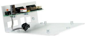
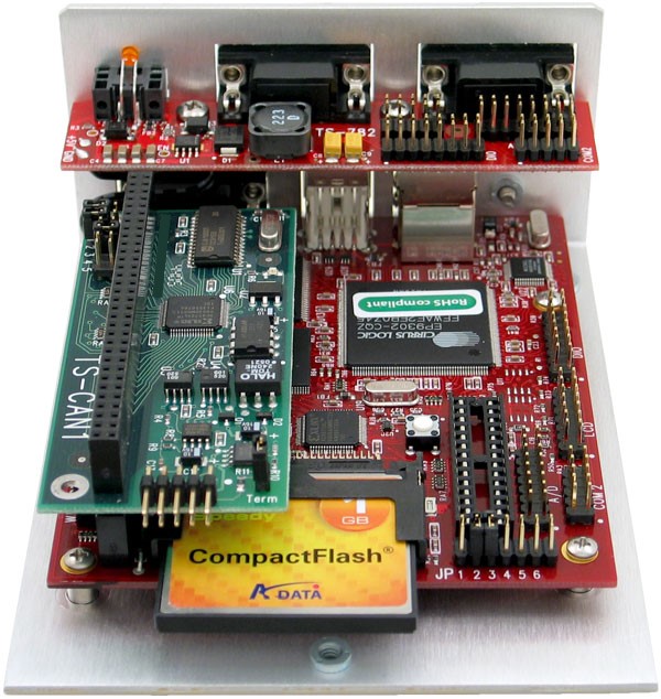
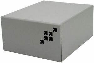
The TS-ENC720 metal enclosure is made to house the TS-7200, TS-7250, TS-7260, TS-7350, TS-7800, TS-8100, or TS-8160 Single Board Computer and two PC/104 peripheral boards. The switching power regulator efficiently converts 8-30 VDC input (8-38 VDC for the TS-7800) into regulated +5 VDC required by the SBC.
Note that the TS-DIO64 and the TS-9700 with the DAC option both have connectors that do not fit into the TS-ENC720. The second Ethernet or reset button of the TS-8100 or TS-8160 is not compatible with this enclosure.
The TS-ENC720 Rugged Enclosure provides extra functions, including power conversion and DB9 breakouts of the internal COM ports or additional I/O. Additional features include:
- Supports TS-7200 family and TS-7800
- Power converter: 8-30VDC to 5VDC
- 8-38VDC to 5VDC for the TS-7800
- Surge suppression on power input
- Sturdy metal design reduces noise
- COM ports adapted to 9 pin Sub-D
- Dimensions 2-1/2x4-3/8x5-3/8 inch
- Power good LED visible
- Ethernet Status LEDs visible
- Extra DB9: COM3 or 8 DIO or 8 A/D
Getting Started
Handling the Board Safely
Before performing any set up or placement procedures, take precautions outlines in this section.
- Be sure to take appropriate Electrostatic Discharge (ESD) precautions.
- Disconnect the power cable at the rear panel of the enclosure before moving,
cabling, or performing any set up procedures.
| WARNING: | Inappropriate handling may cause damage to the board inside |
Setup and Installation Instructions
Follow these guidelines for safety and maximum product performance:
- Observe local health and safety requirements and guidelines for manual material
- ndling.
- Set the enclosure on a level surface with adequate ventilation.
- Ensure the rubber feet are used for protection and stability on level surfaces.
- Wall-mount the unit if placement on a level surface is not available, or desired.
Setup Tools
Depending on placement and cabling of the enclosure, you may need the following tools:
- Small flat-blade screwdriver
- Small Phillips screwdriver
Setup Procedures
After locating, setting up, grounding, and cabling the enclosure:
- Apply power to the unit (refer to some other section)
- Monitor COM1 using a terminal emulator to verify that the enclosure is operating properly
Disconnecting AC Power
- Unplug the cord from the power source
- Disconnect the power cord from the rear panel of the enclosure
Components
TS-782
The TS-782 is the board inserted in to the TS-ENC720 that provides the internal SBC with 2 DB-9 ports and 5VDC power regulation.
Front and Rear Panels
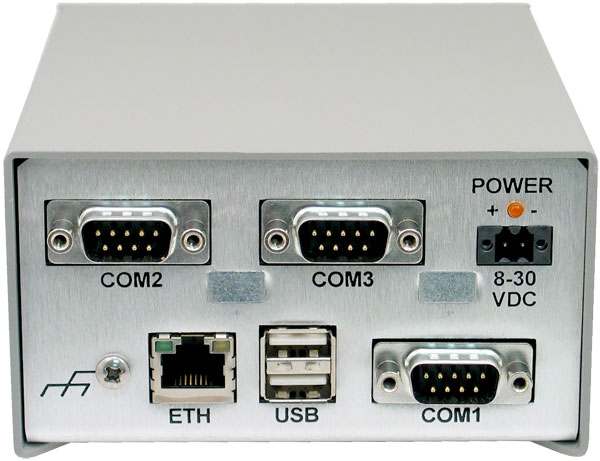
The TS-ENC720 front panel is shown on the first page of this manual.
The rear panel of the TS-ENC720 enclosure (shown above) has all of the input/output connectors, including one COM port, two DB9 ports which can be used for an additional COM port, 8 channel A/D, or 8 DIO pins, one ethernet port, two USB ports, two pin power connector, as well as a power indicator LED.
Standard Headers and Connectors
COM1: Console RS-232 Serial Port
The COM1 RS-232 port uses a standard DB-9 male connector on the TS-ENC720.
| DB9 Pin | Signal | Description |
|---|---|---|
| 1 | DCD | Data Carrier Detect |
| 2 | RXD | Receive data |
| 3 | TXD | Transmit data |
| 4 | DTR | Data Terminal Ready |
| 5 | GND | Ground |
| 6 | DSR | Data Set Ready |
| 7 | RTS | Request to Send |
| 8 | CTS | Clear to Send |
| 9 | - | - |
| Note: | The COM1 port on the TS-ENC720 is the default port used for system console. The RC-DB9 cable must be connected to COM1 in order to have a Linux console via any terminal emulator. |
USB
The USB Connector on the TS-ENC720 provide two USB interfaces for the user. These are directly connected to the EP9302 processor, which integrates an USB dual-port Open Host Controller Interface (Open HCI), providing full-speed serial communications ports at a baud rate of 12 Mbits/sec. Up to 127 USB devices (printer, mouse, camera, keyboard, etc.) and USB hubs can be connected to the USB host in the USB "tiered-star" topology.
ETH0
The ethernet connector ETH0 makes use of a standard RJ-45 socket. This can be used to connect a standard 10/100 Ethernet cable into the enclosed SBC.
COM2 and COM3
Two standard DB-9 connectors are brought out for additional COM ports, DIO, or A/D conversion. The DB-9 headers are connected straight to the enclosed SBC. COM2 header is designed to connect to the A/D (MAX197 on TS-7200/TS-7250) header on the enclosed SBC and COM3 is designed for the DIO1 (or XDIO/DIO2 on the TS-7260) header of the enclosed SBC. Both COM2 and COM3 are set up to connect to COM headers on the enclosed SBC.
| WARNING: | Connecting both RS-232 signals and DIO or A/D to the same COM port may cause irreversible damage to the SBC |
| DB-9 Pin | COM3 (DIO) | COM2 (TS-7200 & TS-7250 MAX197 A/D) | COM2/COM3 (TS-7250 & TS-7800 10 pin On-board A/D) | COM2/COM3 (RS-232) |
|---|---|---|---|---|
| 1 | DIO_0 | Ch0 | Ch0 | DCD |
| 2 | DIO_1 | Ch1 | GND | RXD |
| 3 | DIO_2 | Ch2 | Ch1 | TXD |
| 4 | DIO_3 | Ch3 | GND | DTR |
| 5 | GND | GND | Ch2 | GND |
| 6 | DIO_4 | Ch4 | GND | DSR |
| 7 | DIO_5 | Ch5 | Ch3 | RTS |
| 8 | DIO_6 | Ch6 | GND | CTS |
| 9 | DIO_7 | Ch7 | Ch4 | -- |
| Note: | Other configurations are possible, but they may require non-standard cabling |
TS-782 Routing/Connectors
The TS-782 board creates an interface between the TS-72XX/TS-7800 and external connections (The two DB-9 ports and incoming power connections).
TS-782 Internal Headers
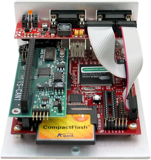
Both of the DB-9 connectors on the TS-782 have a 16-pin and a 10-pin male header. These allow for connection to the SBCs COM port, DIO, or A/D converter. Technologic Systems provides: one 10-pin and one 16-pin cable (and an additional 10-pin and 16-pin cable with the A/D option) for TS-7200/TS-7250; two 10-pin cables for the TS-7260/TS- 7800.
TS-782 Internal Power Cable
The internal power cable of the TS-782 must be connected to the power input of the enclosed SBC in order to provide regulated 5VDC power supply to the SBC.
| WARNING: | The indicated polarity must be used when connecting this cable |
Product Specifications
Dimensions
The TS-ENC720 enclosure dimensions are 2.5" x 4.375" x 5.375"
Cabling
The enclosure includes the following cables for use with the TS-72XX/TS-7800 SBCs:
- All internal ribbon cables to make connections between the various 10-pin headers
Environmental
To ensure optimum product operation you must maintain the operational environmental specifications listed in the table below.
| Environmental Specifications | Standard Temp Products | Extended Temp Products |
|---|---|---|
| Ambient Temperature | -20° to +70°C The internal temperature must not exceed +70°C |
-40° to +85°C Extended temperature is also standard lower CPU clock speeds. Note: At high temperature operations, CPU clock speed should be set to <= 166MHz Note: Refer to your product manual, or contact Customer Service at Technologic Systems if the environmental temperature of the location is in doubt. |
| Relative Humidity | 0 to 90% relative humidity. Not to exceed 90% non-condensing | Not to exceed 90% non-condensing |
